This is an old revision of the document!
Table of Contents
LED strips!
We love some good LED blinking as much as the next person but after years of LED-soldering we need something cooler to get us excited. Sure there are RGB LEDs and those are fun too but what comes after that? Well, we have the answer: LED Strips! These are flexible circuit boards with full color LEDs soldered on. They take a lot of LED-wiring-drudgery out of decorating a room, car, bicycle, costume, etc. The ones we carry are also waterproof (although not all are).
There are two basic kinds of LED strips, the "analog" kind and "digital" kind. Analog-type strips have all the LEDs connected in parallel and so it acts like one huge tri-color LED; you can set the entire strip to any color you wan, but you can't control the individual LED's colors. They are very very easy to use and fairly inexpensive.
The Digital-type strips work in a different way. They have a chip for each LED, to use the strip you have to send digitally coded data to the chips. However, this means you can control each LED individually! Because of the extra complexity of the chip, they are more expensive.
"Analog" RGB LED strips
This tutorial is for the Analog RGB LED strips only!
Technical specs:
- 10.5mm (0.41") wide, 3mm (0.12") thick, 100mm (3.95") long per segment
- Clear waterproof molded
- 3M adhesive strip on back
- Maximum 12V @ 60mA draw per strip segment
- 3 common-anode RGB LEDs per segment
- LED wavelengths: 630nm/530nm/475nm
- No microcontroller or chip controller ('analog' only!)
- (We're working on getting an English datasheet from the manufacturer!)
Schematic
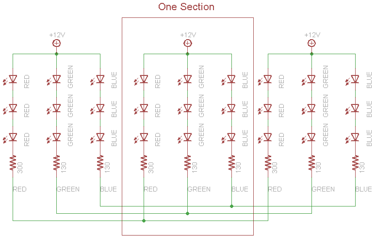
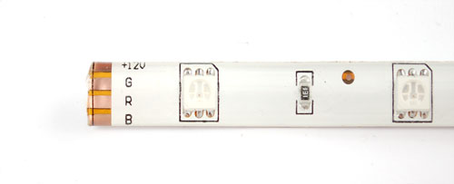
Analog type RGB LED strips come on a reel, and are made of 3-LED sections that are 10 cm long. They are easy to cut at the boundary of each section, theres a little cut mark area and some copper tabs you can solder to. Each LED in a section is a '5050' tri-color type, containing a red, green and blue LED. That means that every section really has 9 total LEDs - three red, three green and three blue. The LEDs are arranged in series as shown in the following schematic:
Current draw
Because there are three LEDs in series, you cannot drive these LEDs from a 5V supply. The LED strips say "+12V" on them to mark the anode and that's the maximum voltage we suggest. We've found that if you're ok with them being a little dimmer, even 9VDC works very well.
Each segment draws approximately 20 milliAmperes from a 12V supply, per string of LEDs. So for each segment, there is a maximum 20mA draw from the red LEDs, 20mA draw from the green and 20mA from the blue. If you have the LED strip on full white (all LEDs lit) that would be 60mA per segment.
To find the total maximum current draw per meter, we would multiply 60mA x 10 (ten segments per meter) = 0.6 Amps per meter. Again, that's assuming you would have all the LEDs on at once and that you are powering it from 12V. If you're going to be PWM-fading between colors, maybe 1/2 of that is what you'll be drawing. Still, you do need to have a fairly decent power supply to run this strip, all those LEDs add up!
Wiring
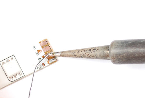
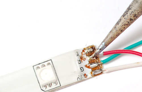
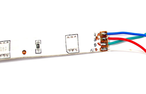
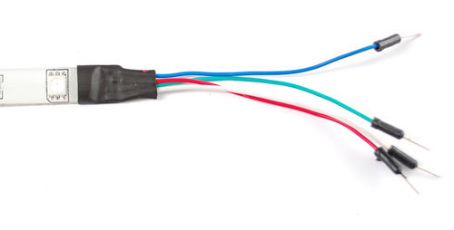
Connecting up to the strip is fairly easy, you'll want to solder four wires to the copper tabs. We'll use white for +12V, then red, green and blue wires for the corresponding LED colors.
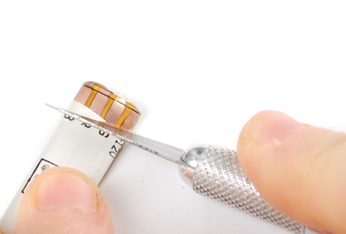
Cut away the waterproof overmolding at one end of the strip. The strips are symmetric so it doesn't matter which end you use
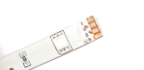
Scrape away the rubber to expose the copper pads
Melt some solder onto the pads to tin them and also burn away any left over rubber
Solder the four wires on. We used stranded wire, which is more flexible and is probably a better choice than solid-core
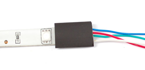
To protect the wires and maintain some waterproofness, you can use heatshrink.
Usage
Because these LED strips are very simple, we can easily use them with any microcontroller. We suggesting using PWM dimming techniques to control the strip. Since each 'LED' pin may end up requiring an Amp or more to sink to ground, power transistors are required! Don't try to connect the pins directly to your everyday microcontroller, they will burn out and/or not work.
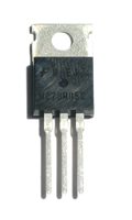
You can use any power NPN or N-Channel MOSFET, make sure the transistor is rated to be able to pass as much current as you need. For example, since we draw about 0.2Amps per channel per meter, if you have a 5 meter strip you will need to pass up to 1 Ampere per transistor. Get the beefy "TO-220" packages, not the dinky little guys. Make sure they look like this:
For basic, low-cost usage we suggest using N-channel MOSFETs such as the STP16NF06 - they are very popular and inexpensive. If you can't get those, TIP120 are also good but there is more voltage loss in a transistor than in a MOSFET which is why we suggest those first (less heat loss, more light!)
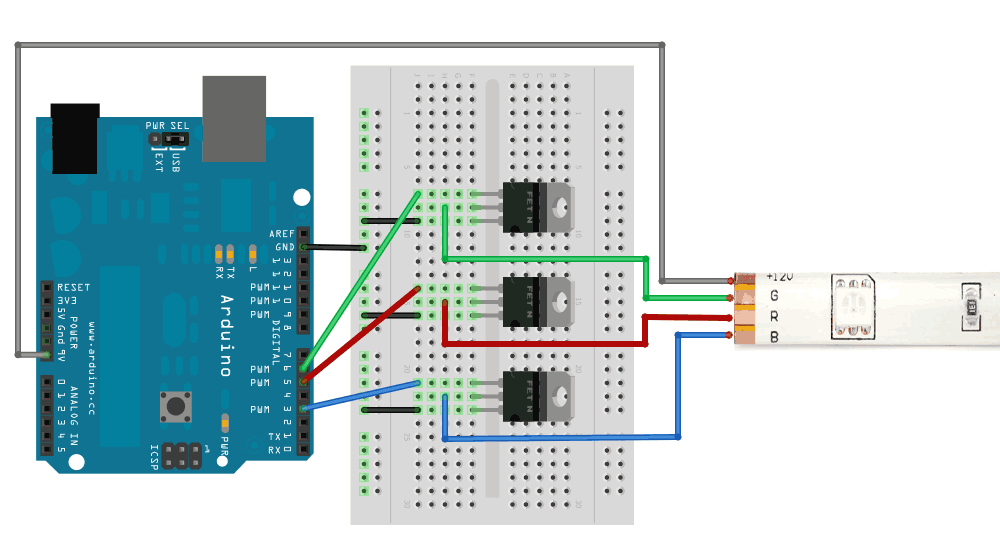
This diagram shows connecting up with N-Channel MOSFETs where the Gate is pin 1, the Drain is pin 2 and the Source is pin 3
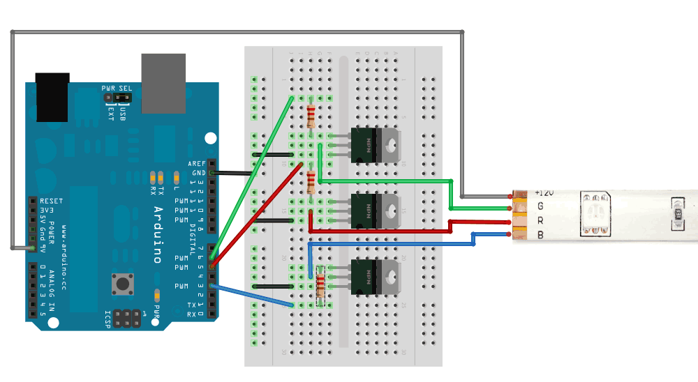
This diagram shows connecting up with power NPN transistors such as TIP120, where Base is pin 1, Collector is pin 2 and Emitter is pin 3. Its very similar except this time we have 100-220 ohm resistors between the PWM output pin and the base.
Connect a 9-12V power supply to the Arduino sot hat Vin supplies the high voltage to the LED strip. If you want, you can also just use a separate wire that connects to a power supply that provides about +12V. Make sure to connect the ground of that supply to the ground of the Arduino/MOSFETs!
Example code
Once you have the strip wired up, it is easy to control the color of the strip by using PWM output, for Arduino you can use analogWrite() on pins 3, 5, 6, 9, 10 or 11 (for classic Arduinos using the Atmega328 or 168). An analogWrite(pin, 0) will turn that LED off, analogWrite(pin, 127) will turn it on half-way and analogWrite(pin, 255) will turn it on full blast. Here is some example code that performs a simple color-swirl.
// color swirl! connect an RGB LED to the PWM pins as indicated
// in the #defines
// public domain, enjoy!

#define REDPIN 5
#define GREENPIN 6
#define BLUEPIN 3

#define FADESPEED 5     // make this higher to slow down

void setup() {
  pinMode(REDPIN, OUTPUT);
  pinMode(GREENPIN, OUTPUT);
  pinMode(BLUEPIN, OUTPUT);
}


void loop() {
  int r, g, b;

  // fade from blue to violet
  for (r = 0; r < 256; r++) {
    analogWrite(REDPIN, r);
    delay(FADESPEED);
  }
  // fade from violet to red
  for (b = 255; b > 0; b--) {
    analogWrite(BLUEPIN, b);
    delay(FADESPEED);
  }
  // fade from red to yellow
  for (g = 0; g < 256; g++) {
    analogWrite(GREENPIN, g);
    delay(FADESPEED);
  }
  // fade from yellow to green
  for (r = 255; r > 0; r--) {
    analogWrite(REDPIN, r);
    delay(FADESPEED);
  }
  // fade from green to teal
  for (b = 0; b < 256; b++) {
    analogWrite(BLUEPIN, b);
    delay(FADESPEED);
  }
  // fade from teal to blue
  for (g = 255; g > 0; g--) {
    analogWrite(GREENPIN, g);
    delay(FADESPEED);
  }
}


