This is an old revision of the document!
Table of Contents
What is a thermocouple?
A thermocouple is a kind of temperature sensor.
Unlike semiconductor temperature sensors such as the TMP36, thermocouples have no electronics inside them, they are simply made by welding together two metal wires. Because of a physical effect of two joined metals, there is a slight but measurable voltage across the wires that increases with temperature. The type of metals used affect the voltage range, cost and sensitivity, which is why we have a few different kinds of thermocouples. The main improvement of using a thermocouple over a semiconductor sensor or thermistor is that the temperature range is very much increased. For example, the TMP36 can go from -50 to 150�C, after that the chip itself can be damaged. Common thermocouples on the other hand, can go from -200�C to 1350�C (K type) and there are ones that can go above 2300�C!
Thermocouples are often used in HVAC systems, heaters and boilers, kilns, etc. There are a few different kinds but this tutorial will discuss K type, which are very common and easiler to interface with.
One difficulty in using them is that the voltage to be measured is very small, with changes of about 50 uV per �C (a uV is 1/1000000 Volts). While it is possible to read these voltages using a clean powersupply and nice opamps, there are other complications such as a non-linear response (its not always 50uV/�C) and cold-temperature compensation (the effect measured is only a differential and there must be a reference, just as ground is a reference for voltage). For that reason, we suggest only using an interface chip that will do the heavy lifting for you, allow you to easily integrate the sensor without as much pain. In this tutorial we will use a MAX6675 K-thermocouple interface chip which doesn't even require an ADC, spitting out a nice digital data signal of the temperature.
Some basic stats
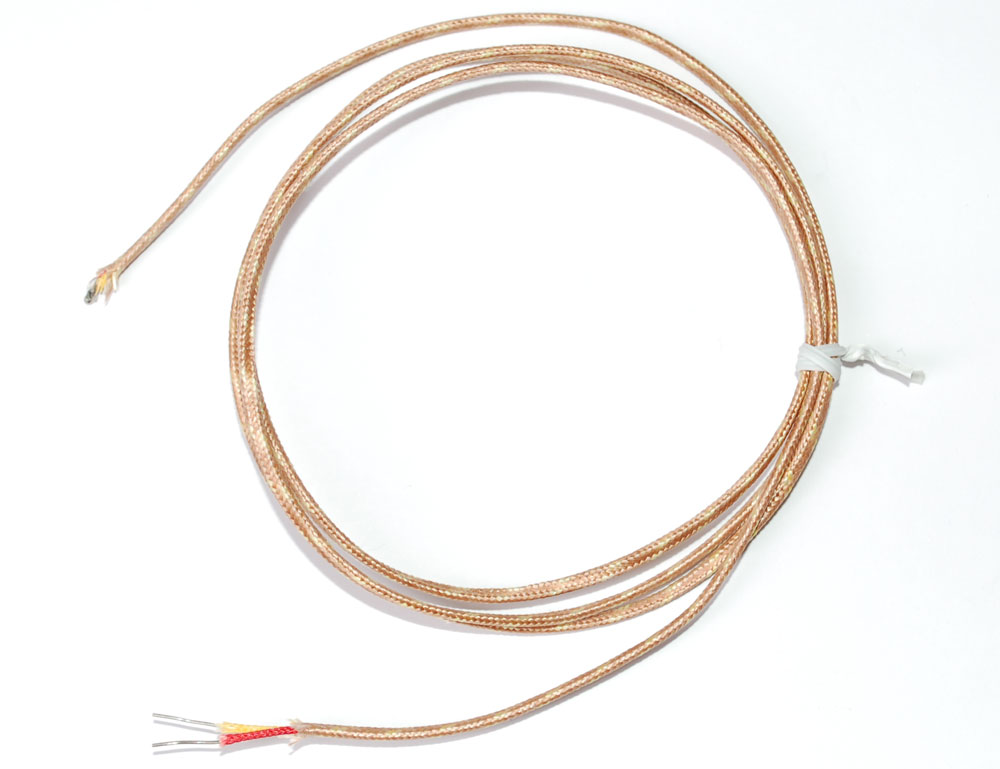
This is for a K-type thermocouple with glass overbraiding
- Size: 24 gauge, 1 meter long (you can cut it down if desired)
- Price: $10 at the adafruit store
- Temperature range: -100�C to 500�C / -150 to 900�F (After this the glass overbraiding may be damaged)
- Output range: -6 to +20mV
- Precision: +-2�C
Files
Wiring
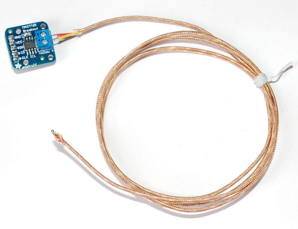
As we mentioned before, trying to actually measure the voltage across the wires will be very difficult for most people, which is why we strongly suggest using a thermocouple interface chip. The nicest one we've seen so far is the MAX6675, which unfortunately is only available in SOIC package. While not too difficult to solder, we nevertheless have in the shop a breakout board that is ready to go. We also suggest the breakout boards from Ryan McLaughlin
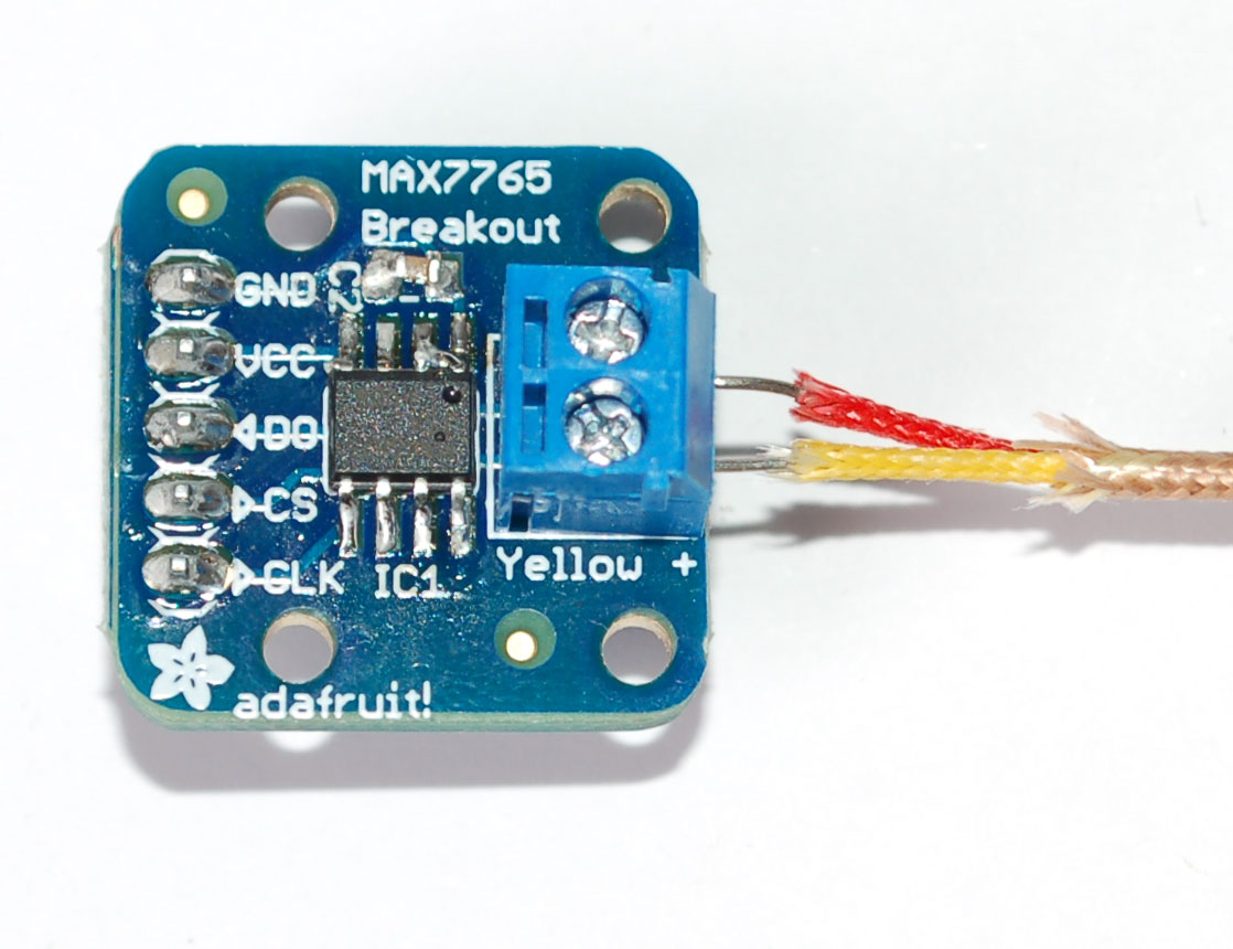
First thing to determine is which wire is which. As you recall, thermocouples are made by welding together two wires, the chip reads the voltage difference between the two. One is the negative (for K-type its made of Alumel) and the other positive (ditto, Chromel). Luckily the wires are color coded, and almost all of the time you'll find the Alumel is red and the Chromel is yellow.
Connect the leads as required to your amplifier:
�
Reading data
If you're using an AD595 interface chip, you can simply connect the voltage output to an analog input on your microcontroller and do some basic math to multiply the 10 mV/�C input into numerical output.
If you're planning to use the MAX6675, there's a little more work to be done. First off, VCC and GND must connect to a 3-5V supply. Then the three data pins must connect to digital IO pins:
- CLK (clock) is an input to the MAX6675 (output from microcontroller) which indicates when to present another bit of data
- DO (data out) is an output from the MAX6675 (input to the microcontroller) which carries each bit of data
- CS (chip select) is an input to the MAX6675 (output from the microcontroller) which tells the chip when its time to read the thermocouple and output more data.
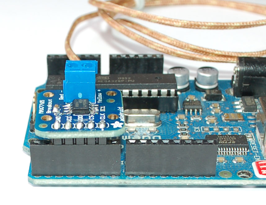
If you're using an Arduino, you can make a little shortcut and simply plug in the pins into the first digital port, from Digital Pin 2 thru 6. (Remember pins 0 and 1 are used by the FTDI chip for uploading)
Then download the MAX6675 Arduino library code by going to the github page and clicking Download Source. Then uncompress the folder and rename it MAX6675 and install it into the library folder according to our handy tutorial.
Restart the Arduino IDE and open up the File→Examples→MAX6675→serialthermocouple sketch and upload it to your Arduino. Once uploaded, open up the serial port monitor to display the current temperatures in both celsius and farenheit

Here is the code
// this example is public domain. enjoy!
// www.ladyada.net/learn/sensors/thermocouple

#include "max6675.h"

int thermoDO = 4;
int thermoCS = 5;
int thermoCLK = 6;

MAX6675 thermocouple(thermoCLK, thermoCS, thermoDO);
int vccPin = 3;
int gndPin = 2;

void setup() {
  Serial.begin(9600);
  // use Arduino pins
  pinMode(vccPin, OUTPUT); digitalWrite(vccPin, HIGH);
  pinMode(gndPin, OUTPUT); digitalWrite(gndPin, LOW);

  Serial.println("MAX6675 test");
  // wait for MAX chip to stabilize
  delay(500);
}

void loop() {
  // basic readout test, just print the current temp

   Serial.print("C = ");
   Serial.println(thermocouple.readCelsius());
   Serial.print("F = ");
   Serial.println(thermocouple.readFarenheit());

   delay(1000);
}
As you can see, its pretty simple to use the library, simply tell the MAX6675 object what the clock, chip select and data pins are, then call readCelsius() or readFarenheit() to get a floating point result. In this example we provide power to the MAX chip via pins 2 and 3 but if you're not just plugging it in as above, you can take out those lines.
Adding a display
A common request is to have the temperature output onto a 'classic' character LCD such as the ones in this tutorial
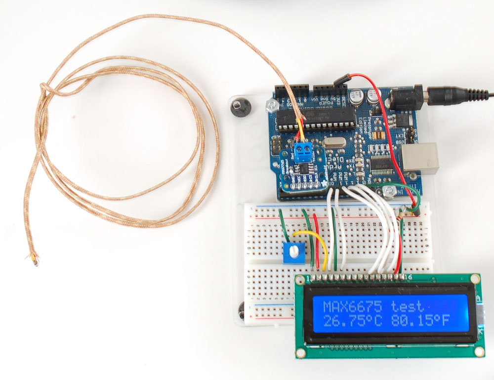
We have an example sketch for this as well. First get the LCD working by following our tutorial. Then move all the wires 1 step to the right so that they use pins 8 thru 13 instead of 7 thru 12. Now load up the new sketch File→Examples→MAX6675→lcdthermocouple and plug in the thermocouple module as we did in the serial thermocouple test, you'll see the temperature displayed in C and F on the second line!
Some projects to check out
Need ideas? Check out these projects!

Jeelabs has a detailed walkthrough for a reflow controller (uses an AD595-type chip)
<object width="640" height="385"><param name="movie" value="http://www.youtube.com/v/Sb1nvKYYTdc&hl=en_US&fs=1"></param><param name="allowFullScreen" value="true"></param><param name="allowscriptaccess" value="always"></param></object>
Thermocouple to RGB LED


