This is an old revision of the document!
Table of Contents
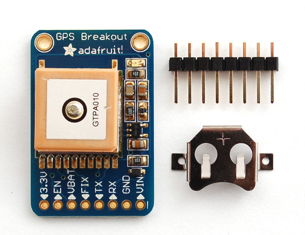
\We carry a few different GPS modules here in the Adafruit shop, but none that satisfied our every desire - that's why we designed this little GPS breakout board. We believe this is the Ultimate GPS module, so we named it that. It's got everything you want and more, with -165 dBm sensitivity, 5V friendly design, breadboard friendly, mounting holes, 10 Hz updates, 66 channels, RTC battery-compatible and has a status LED all for under $40! The newest version we carry (using the MTK3339 chipset, as of March 26th) adds built in datalogging capability and high altitude functionality with even lower power.
The breakout is built around the MTK3339 chipset, a no-nonsense, high-quality GPS module that can track up to 22 satellites on 66 channels, has an excellent high-sensitivity receiver (-165 dB tracking!), and a built in antenna. It can do up to 10 location updates a second for high speed, high sensitivity logging or tracking. Power usage is incredibly low, only 20 mA during navigation.
Best of all, we added all the extra goodies you could ever want: a ultra-low dropout 3.3V regulator so you can power it with 3.3-5VDC in, 5V level safe inputs, ENABLE pin so you can turn off the module using any microcontroller pin or switch, a footprint for optional CR1220 coin cell to keep the RTC running and allow warm starts and a tiny bright red LED. The LED blinks at about 1Hz while it's searching for satellites and blinks once every 15 seconds when a fix is found to conserve power. If you want to have an LED on all the time, we also provide the FIX signal out on a pin so you can put an external LED on.
Two things that really stand out about the new MTK3339-based module is the high-altitude functionality and the the built in data-logging capability. Most modules permit NMEA output only when the module is traveling under 515 m/s AND when its at an altitude of under 60,000 ft (18,000 m). This is to prevent the modules from being used for military use. However, as the requirements are not as strict, we've requested the factory to keep the speed limit but remove the altitude restriction. We trust that the factory has removed the limit but we have not done independent verification yet. If this feature is critical, please do not purchase until we've personally verified it!
The other cool feature of the new MTK3339-based module (which we have tested with great success) is the built in datalogging ability. Since there is a microcontroller inside the module, with some empty FLASH memory, the newest firmware now allows sending commands to do internal logging to that FLASH. The only thing is that you do need to have a microcontroller send the "Start Logging" command. However, after that message is sent, the microcontroller can go to sleep and does not need to wake up to talk to the GPS anymore to reduce power consumption. The time, date, longitude, latitude, and height is logged every 15 seconds and only when there is a fix. The internal FLASH can store about 16 hours of data, it will automatically append data so you don't have to worry about accidentally losing data if power is lost. It is not possible to change what is logged and how often, as its hardcoded into the module but we found that this arrangement covers many of the most common GPS datalogging requirements.
Specifications
Module specs:
- Satellites: 22 tracking, 66 searching
- Patch Antenna Size: 15mm x 15mm x 4mm
- Update rate: 1 to 10 Hz
- Position Accuracy: 1.8 meters
- Velocity Accuracy: 0.1 meters/s
- Warm/cold start: 34 seconds
- Acquisition sensitivity: -145 dBm
- Tracking sensitivity: -165 dBm
- Maximum Altitude for MTK3329: 18,000 meters
- Maximum Altitude for MTK3339: no limit
- Maximum Velocity: 515m/s
- Vin range: 3.0-5.5VDC
- MTK3329 Operating current: 48mA tracking, 37 mA current draw during navigation
- MTK3339 Operating current: 25mA tracking, 20 mA current draw during navigation
- Output: NMEA 0183, 9600 baud default
- DGPS/WAAS/EGNOS supported
- FCC E911 compliance and AGPS support (Offline mode : EPO valid up to 14 days )
- Up to 210 PRN channels
- Jammer detection and reduction
- Multi-path detection and compensation
Breakout board details:
- Weight (not including coin cell or holder): 8.5g
- Dimensions (not including coin cell or holder): 23mm x 35mm x 8mm / 0.9" x 1.35" x 0.3"
If you purchased a module before March 26th, 2012 and it says MTK3329 on the silkscreen, you have the version of this breakout with the MT3329 chipset. The MTK3329 does not have high-altitude capability or built in datalogging. If your module has sharpie marker crossking out the MTK3329 text or there is no text, you have an MTK3339. This tutorial assumes you have a '3339 type module.
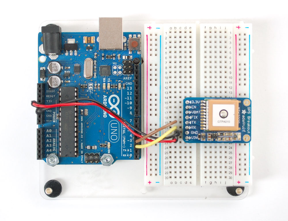
Direct Computer Wiring
GPS modules are great in that the moment you turn them on, they'll start spitting out data, and trying to get a 'fix' (location verification). Like pretty much every GPS in existance, the Adafruit Ultimate GPS uses TTL serial output to send data so the best way to first test the GPS is to wire it directly to the computer via the TTL serial to USB converter on an Arduino. You can also use an FTDI Friend or other TTL adapter but for this demonstation we'll use a classic Arduino.
First, load a 'blank' sketch into the Arduino:
// this sketch will allow you to bypass the Atmega chip
// and connect the fingerprint sensor directly to the USB/Serial
// chip converter.

// Connect VIN to +5V
// Connect GND to Ground
// Connect GPS RX (data into GPS) to Digital 0
// Connect GPS TX (data out from GPS) to Digital 1

void setup() {}
void loop() {}
This is will free up the converter so you can directly wire and bypass the Arduino chip. Once you've uploaded this sketch, wire the GPS as follows:
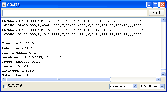
Now plug in the USB cable, and open up the serial monitor from the Arduino IDE and be sure to select 9600 baud in the drop down. You should see text like the following
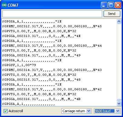
This is the raw GPS "NMEA sentence" output from the module. There are a few different kinds of NMEA sentences, the most common ones people use are the $GPRMC (Global Positioning Recommended Minimum Coordinates or something like that) and the $GPGGA sentences. These two provide the time, date, latitude, longitude, altitude, estimated land speed, and fix type. Fix type indicates whether the GPS has locked onto the satellite data and received enough data to determine the location (2D fix) or location+altitude (3D fix).
For more details about NMEA sentences and what data they contain, check out this site
If you look at the data in the above window, you can see that there are a lot of commas, with no data in between them. That's because this module is on my desk, indoors, and does not have a 'fix'. To get a fix, we need to put the module outside.
GPS modules will always send data EVEN IF THEY DO NOT HAVE A FIX! In order to get 'valid' (not-blank) data you must have the GPS module directly outside, with the square ceramic antenna pointing up with a clear sky view. In ideal conditions, the module can get a fix in under 45 seconds. however depending on your location, satellite configuration, solar flares, tall buildings nearby, RF noise, etc it may take up to half an hour (or more) to get a fix! This does not mean your GPS module is broken, the GPS module will always work as fast as it can to get a fix.
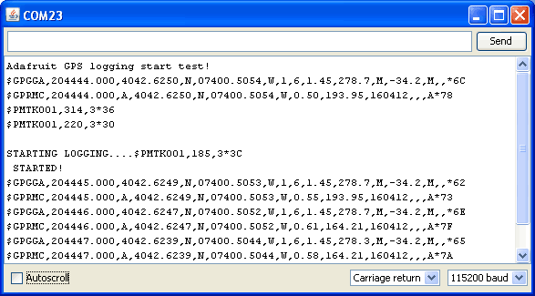
If you can get a really long USB cord, and stick the GPS out a window, so its pointing at the sky, eventually the GPS will get a fix and the window data will change over to transmit valid data like this:
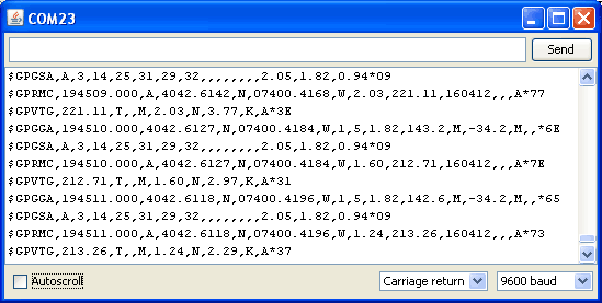
Look for the line that says $GPRMC,194509.000,A,4042.6142,N,07400.4168,W,2.03,221.11,160412,,,A*77
This line is called the RMC (Recommended Minimum) sentence and has pretty much all of the most useful data. Each chunk of data is seperated by a comma.
The first part 194509.000 is the current time GMT. The first two numbers 19 indicate the hour (1900h, otherwise known as 7pm) the next two are the minute, the next two are the seconds and finally the millseconds. So the time when this screenshot was taken is 7:45 pm and 9 seconds
The second part is the 'status code', if it is a V that means the data is Void (invalid). If it is an A that means its Active (the GPS could get a lock/fix)
The next 4 pieces of data are the geolocation data. According to the GPS, my location is 4042.6142,N (Latitude 40 degrees, 42.3932 minutes North) & 07400.4168,W. (Longitude 74 degrees, 0.4680 minutes West) To look at this location in Google maps, type +40° 42.6142', -74° 00.4168' into the google maps search box. Unfortunately gmaps requires you to use +/- instead of NSWE notaion. N and E are postive, S and W are negative.
The next data is the ground speed in knots. We're going 2.03 knots
After that is the tracking angle, this is meant to approximate what 'compass' direction we're heading at based on our past travel
The one after that is 160412 which is the current date (16th of April, 2012).
Finally there is the *XX data which is used as a data transfer checksum
Once you get a fix using your GPS module, verify your location with google maps (or some other mapping software). Remember that GPS is often only accurate to 5-10 meters and worse if you're indoors or surrounded by tall buildings.
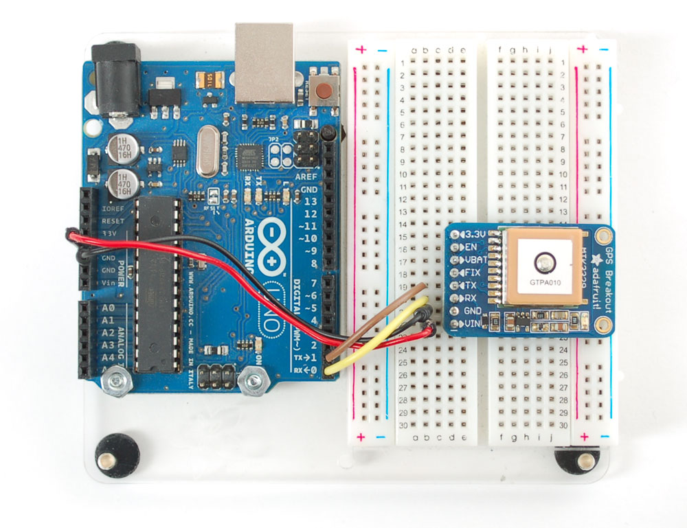
Arduino Wiring
Once you've gotten the GPS module tested with direct wiring, we can go forward and wire it up to a microcontroller. We'll be using an Arduino but you can adapt our code to any other microcontroller that can receive TTL serial at 9600 baud
Connect VIN to +5V, GND to Ground, RX to digital 2 and TX to digital 3
Next up, download the Adafruit GPS library. This library does a lot of the 'heavy lifting' required for receiving data from GPS modules, such as reading the steaming data in a background interrupt and automagically parsing it. To download it, visit the GitHub repository and click the DOWNLOADS button in the top right corner, rename the uncompressed folder Adafruit_GPS. Check that the Adafruit_GPS folder contains Adafruit_GPS.cpp and Adafruit_GPS.hPlace the Adafruit_GPS library folder your <arduinosketchfolder>/libraries/ folder. You may need to create the libraries subfolder if its your first library. Restart the IDE.
Open up the File→Examples→Adafruit_GPS→echo sketch and upload it to the Arduino. Then open up the serial monitor. This sketch simply reads data from the software serial port (pins 2&3) and outputs that to the hardware serial port connected to USB.
You can configure the output you see by commenting/uncommenting lines in the setup() procedure. For example, we can ask the GPS to send different sentences, and change how often it sends data. 10 Hz (10 times a second) is the max speed, and is a lot of data. You may not be able to output "all data" at that speed because the 9600 baud rate is not fast enough.
  // You can adjust which sentences to have the module emit, below

  // uncomment this line to turn on RMC (recommended minimum) and GGA (fix data) including altitude
  GPS.sendCommand(PMTK_SET_NMEA_OUTPUT_RMCGGA);
  // uncomment this line to turn on only the "minimum recommended" data for high update rates!
  //GPS.sendCommand(PMTK_SET_NMEA_OUTPUT_RMCONLY);
  // uncomment this line to turn on all the available data - for 9600 baud you'll want 1 Hz rate
  //GPS.sendCommand(PMTK_SET_NMEA_OUTPUT_ALLDATA);

  // Set the update rate
  // 1 Hz update rate
  //GPS.sendCommand(PMTK_SET_NMEA_UPDATE_1HZ);
  // 5 Hz update rate- for 9600 baud you'll have to set the output to RMC or RMCGGA only (see above)
  GPS.sendCommand(PMTK_SET_NMEA_UPDATE_5HZ);
  // 10 Hz update rate - for 9600 baud you'll have to set the output to RMC only (see above)
  //GPS.sendCommand(PMTK_SET_NMEA_UPDATE_10HZ);
In general, we find that most projects only need the RMC and GGA NMEA's so you don't need ALLDATA unless you have some need to know satellite locations.
Parsed output
Since all GPS's output NMEA sentences and often for our projects we need to extract the actual data from them, we've simplified the task tremendously when using the Adafruit GPS library. By having the library read, store and parse the data in a background interrupt it becomes trivial to query the library and get the latest updated information without any icky parsing work.
Open up the File→Examples→Adafruit_GPS→parsing sketch and upload it to the Arduino. Then open up the serial monitor.
In this sketch, we call GPS.read() within a once-a-millisecond timer (this is the same timer that runs the millis() command). Then in the main loop we can ask if a new chunk of data has been received by calling GPS.newNMEAreceived(), if this returns true then we can ask the library to parse that data with GPS.parse(GPS.lastNMEA()).
We do have to keep querying and parsing in the main loop - its not possible to do this in an interrupt because then we'd be dropping GPS data by accident.
Once data is parsed, we can just ask for data from the library like GPS.day, GPS.month and GPS.year for the current date. GPS.fix will be 1 if there is a fix, 0 if there is none. If we have a fix then we can ask for GPS.latitude, GPS.longitude, GPS.speed (in knots, not mph or k/hr!), GPS.angle, GPS.altitude (in centimeters) and GPS.satellites (number of satellites)
This should make it much easier to have location-based projects. We suggest keeping the update rate at 1Hz and request that the GPS only output RMC and GGA as the parser does not keep track of other data anyways.
Battery Backup
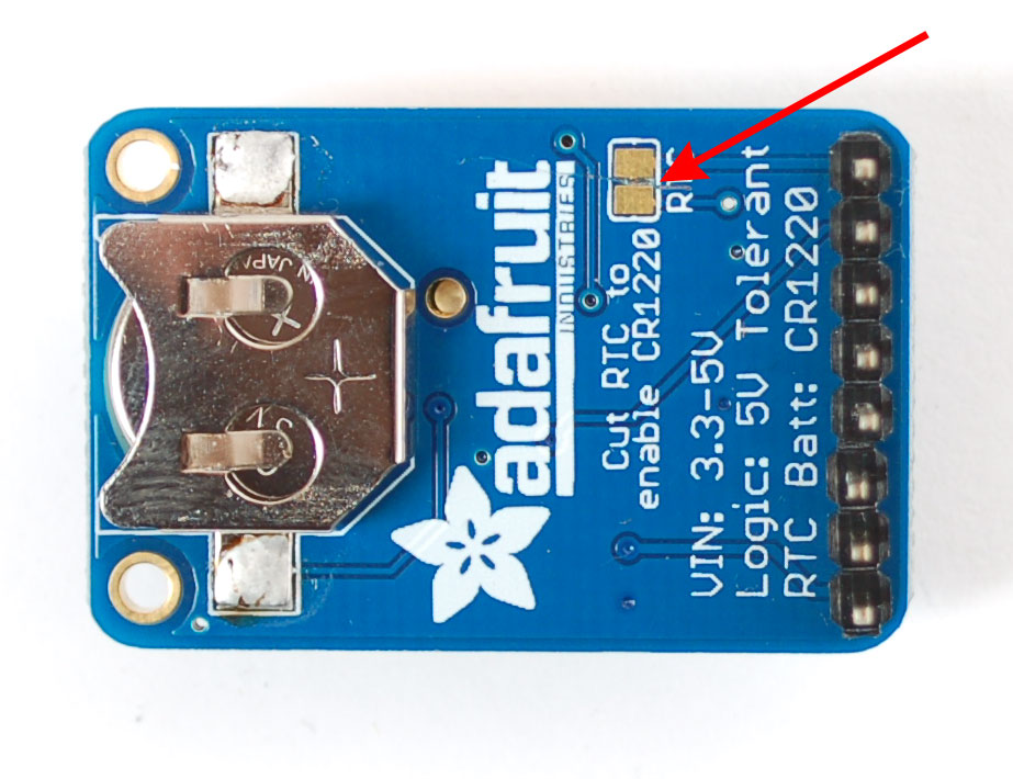
The GPS has a built in real time clock, which can keep track of time even when it power is lost and it doesn't have a fix yet. It can also help reduce fix times, if you expect to have a flakey power connection (say you're using solar or similar). To use the RTC, we need to attach a battery. There is a spot on the back for a CR1220 sized battery holder. We provide the holder but the battery is not included. You can use any 12mm coin cell - these are popular and we also carry them in the Adafruit shop.
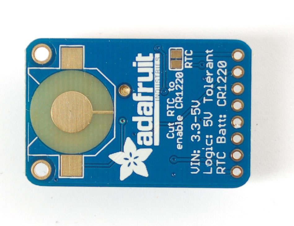
Before inserting a battery into the battery holder, first cut the trace between the two solder pads on the back, labeled RTC (this disconnects the VIN pin from the battery input) Use a multimeter with continuity checking to verify the two pads are no longer tied together.
Advanced Wiring
Thus far we've only used the VIN GND TX and RX pins of the GPS - but there are many other pins. What do these do and will you ever need them? Chances are, for 90% of GPS projects, the other pins are not required. But we do make them available in case you have a specific need.
FIX is an output pin - it is the same pin as the one that drives the red LED. When there is no fix, the FIX pin is going to pulse up and down once every second. When there is a fix, the pin is low (0V) for most of the time, once every 15 seconds it will pulse high for 200 milliseconds
VBAT is an input pin - it is connected to the GPS real time clock battery backup. We suggest using the battery spot on the back but if you have a project with a coin cell or other kind of battery that you want to use (and its under 3.3V) you can connect it to the VBAT pin. If you do this, be sure to cut the trace on the back between the RTC solder pads
EN is the Enable pin, it is pulled high with a 10K resistor. When this pin is pulled to ground, it will turn off the GPS module. This can be handy for very low power projects where you want to easily turn the module off for long periods. You will lose your fix if you disable the GPS so keep that in mind.
3.3V is the output from the onboard 3.3V regulator. If you have a need for a clean 3.3V output, you can use this! It can provide at least 100mA output.
Built in Logging
One of the nice things about the MTK3339 is the built in data-logger. This basic data-logging capability can store date, time, latitude, longitude and altitude data into a 64K flash chip inside. Its not a high resolution logger - it only logs once every 15 seconds when there is a fix - but for 99% of projects that want to track location, this can be a great low power way to log data - no SD card or other EEPROM required! It can store up to 16 hours of data.
The GPS module does require a microcontroller to 'kick start' the logger by requesting it to start. If power is lost it will require another 'kick' to start. If you already have some data in the FLASH, a new trace will be created (so you wont lose old data) and if you run out of space it will simply halt and not overwrite old data. Despite this annoyance, its still a very nice extra and we have some library support to help you use it
First, we should try getting the logger to run.Open up the File→Examples→Adafruit_GPS→locus_start sketch. This will demonstrate how to start the logger (called LOCUS)
The key part is here:
  Serial.print("STARTING LOGGING....");
  if (GPS.LOCUS_StartLogger())
    Serial.println(" STARTED!");
  else
    Serial.println(" no response :(");
  delay(1000);
You should start the logger and then check the response
Once you've seen that the GPS is OK with logging, you can load up the status sketch which will also give you more data. Upload File→Examples→Adafruit_GPS→locus_status
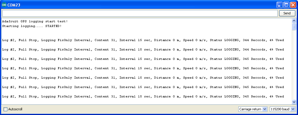
This output gives you some more information. the first entry is the Log #. This is how many log traces are in the memory. Every time you start and save data, a new log is made. Full Stop means that once the logger has run out of memory it will stop. Next the output indicates that we are logging only during fix data and at set intervals, with an interval delay of 15 seconds. We are not logging based on distance or speed. The current status is LOGGING (active), there's also the number of records we've stored. Each record is a timestamped location. We log once every 15 seconds, you can see the records increment from 344 to 345 here. Lastly, we can see how much of the internal flash storage is used, only 4% at this point
In real use, you'll probably want to start the loggging and then have your microcontroller go to sleep to reserve power, waking up once in a while to check up on the logging status.
Finally, once we're done logging we need to extract the data. To do this we need to first get the raw data out of the FLASH and then decode the sentences. Upload File→Examples→Adafruit_GPS→locus_dump to the Arduino and open up the serial monitor
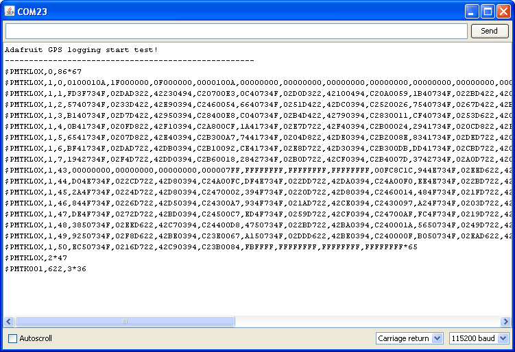
Copy and paste all the text after the —-'s (starting with $PMTKLOX,0,86*67 and ending with $PMTK001,622,3*36) then paste it into the following box:
| XML Output: |
KML Output: |
Downloads & Resources
- MTK3329/MTK3339 command set sheet for changing the fix data rate, baud rate, sentence outputs, etc!
More reading:
