Table of Contents
Whatsit?
This is just a couple tips and tricks I've figured out on how to use fiducials. Specifically, its for our MDC 7722FV pick and place but theres a good chance that whatever p&p you're designing PCBs for, its gonna be the same.
What are they?
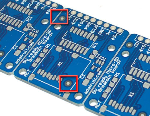
Fiducials are little target registration marks that are printed on PCBs, they are placed on the top copper layer (and bottom if you're doing 2-layers) and allow the vision system of the pick and place to recognize where the PCB is at. They are not placed on the mask or silk because they are not as precisely aligned to the parts as the copper itself.
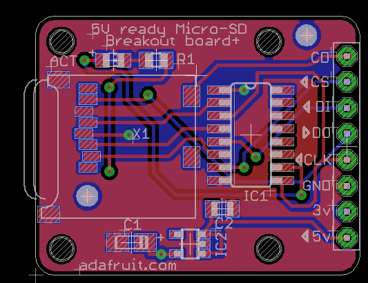
We use 2 fiducials on either corner of the PCB. The farther away they are, the better the precision. Opposite corners allow for skew correction.
Mask
The key on getting good recognition is that there must not be anything around the fiducial so that there is a 'matte' background. That means putting a Stop mask on top and then also a Keepout around it so that no planes or traces are within say 1 diameter's length away
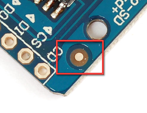
For example, here is a good fiducial, with a shiny silver dot surrounded by empty blank PCB: no copper, no mask.
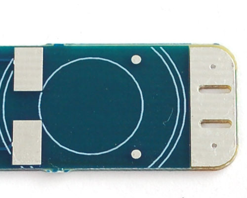
Here is a not-so-good fiducial, with a shiny dot but no keepout…these cause more problems
Shape & Size
I find 1mm diameter circles work just fine. Depending on the machine, you may be better off with smaller (less space wasted) or larger (if the vision system needs it). Ask the contract manufacturer what they'd like before you get PCBs made. You can get our 1mm fiducial part footprint from our eagle library!
MDC 7722FV
Here are my notes for the pick and place!
For the 1mm fiducial, we use the following part definition:
| Part | Nozzle | dx0 | dy0 | st | da9 | X | Y | Pt | W | Thick | LunaVis | TS | Level | Type | Voff | Remark |
|---|---|---|---|---|---|---|---|---|---|---|---|---|---|---|---|---|
| 1mm fiducial | 2 | 0 | 0 | 0 | 0 | 2 | 2 | 0 | 0 | 1 | 1 | 50 | 0.9 | MARK3 | 1mmfi |
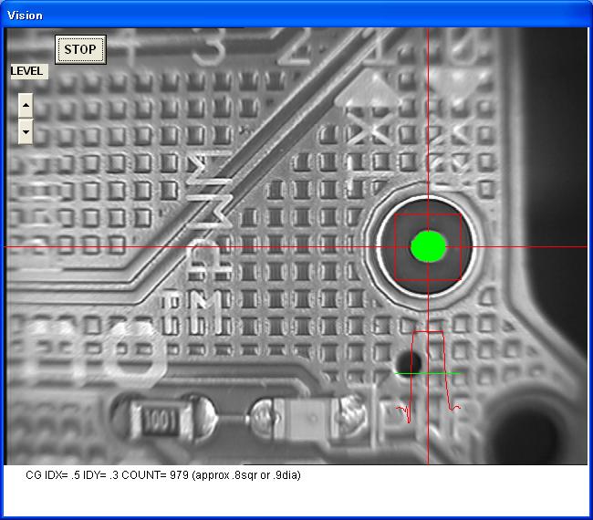
Basically, define a 1mm dot with a 2mm window. you can mess with Level but 0.9 seems good to us
In the PCB parts placement, set one fiducial to Feeder #261 and the other to #262
If you want the fiducials to be checked for each board of a step&repeat, set the Angle to be nonzero - I use '1'. If Angle = 0 it will only check the first PCB in the repeat!
Make sure you set the Bias point first so that you have that correct, we put the fid's as the first two elements in the PCB parts.
Offsetting
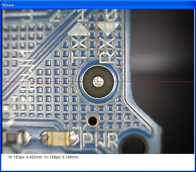
One problem that may occur with fiducials is the harsh direct light from the top vision may create 'bumps' that show up dark, confusing the vision detection. This is due to the solder surface being uneven, the shadows show up particularly well as seen here:
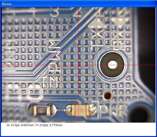
Try reducing the Level to 0.8 or 0.9. If that doesn't help, a solution is to program in the fiducial with a detection offset, say 4mm in one direction. This way the light is angled, more diffused:
Put 4 into the dx0 column to shift over the vision recognition.
| Part | Nozzle | dx0 | dy0 | st | da9 | X | Y | Pt | W | Thick | LunaVis | TS | Level | Type | Voff | Remark |
|---|---|---|---|---|---|---|---|---|---|---|---|---|---|---|---|---|
| 1mm fiducial | 2 | 4 | 0 | 0 | 0 | 2 | 2 | 0 | 0 | 1 | 1 | 50 | 0.9 | MARK3 | 1mmfi |
You can also try Teach mode, press Shift+S and enter "3,2,2,1,0.9,4" for test (MARK3 type mark, 2mm by 2mm window, 1mm dot, 0.9 Level, 4mm offset)

