Table of Contents
Introduction
This is a quick tutorial for our 128x64 and 128x32 pixel monochrome OLED displays. These displays are small, only about 1" diameter, but very readable due to the high contrast of an OLED display. Each OLED display is made of 128x64 or 128x32 individual white OLEDs, each one is turned on or off by the controller chip. Because the display makes its own light, no backlight is required. This reduces the power required to run the OLED and is why the display has such high contrast; we really like this miniature display for its crispness!
The driver chip, SSD1306 can communicate in multiple ways including I2C, SPI and 8-bit parallel. However, only the 128x64 display has all these interfaces available. For the 128x32 OLED, only SPI is available. Frankly, we prefer SPI since its the most flexible and uses a small number of I/O pins so our example code and wiring diagram will use that.
OLED Power requirements
The OLED and driver require a 3.3V power supply and 3.3V logic levels for communication. The power requirements depend a little on how much of the display is lit but on average the display uses about 20mA from the 3.3V supply. Built into the OLED driver is a simple switch-cap charge pump that turns 3.3v-5v into a high voltage drive for the OLEDs. You can run the entire display off of one 3.3V supply or use 3.3V for the chip power and up to 4.5V for the OLED charge pump or 3.3V for the chip power and a 7-9V supply directly into the OLED high voltage pin.
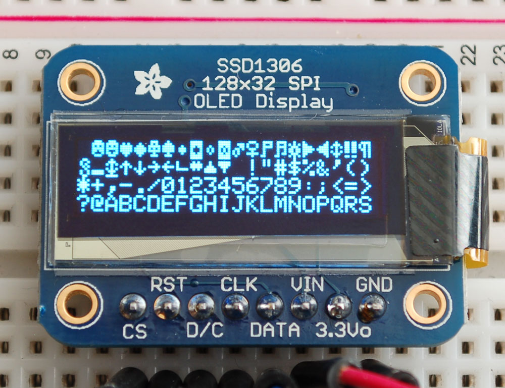
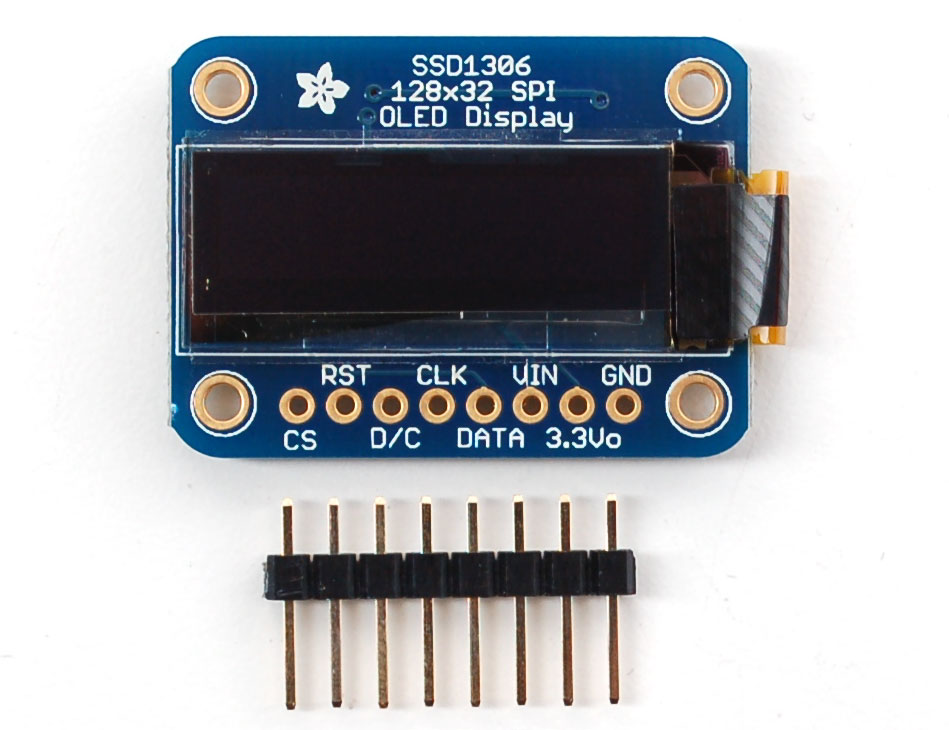
128x32 OLED
The easier of the OLEDs to power is the small SPI one. The OLED is designed to be 5V compatible so you can power it with 3-5V and the onboard regulator will take care of the rest
Simply connect GND to ground, and Vin to a 3 to 5V power supply. There will be a 3.3V output on the 3Vo pin in case you want a regulated 3.3V supply for something else.
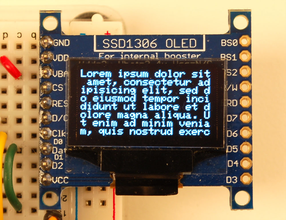
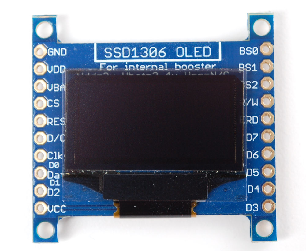
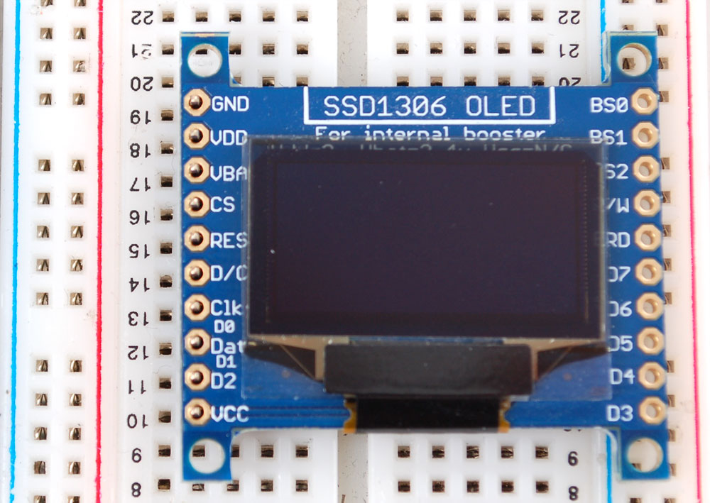
128x64 OLED
The 128x64 OLED is a little more complex to get running as it is not 5V compatible by default, so you have to provide it with 3.3V power
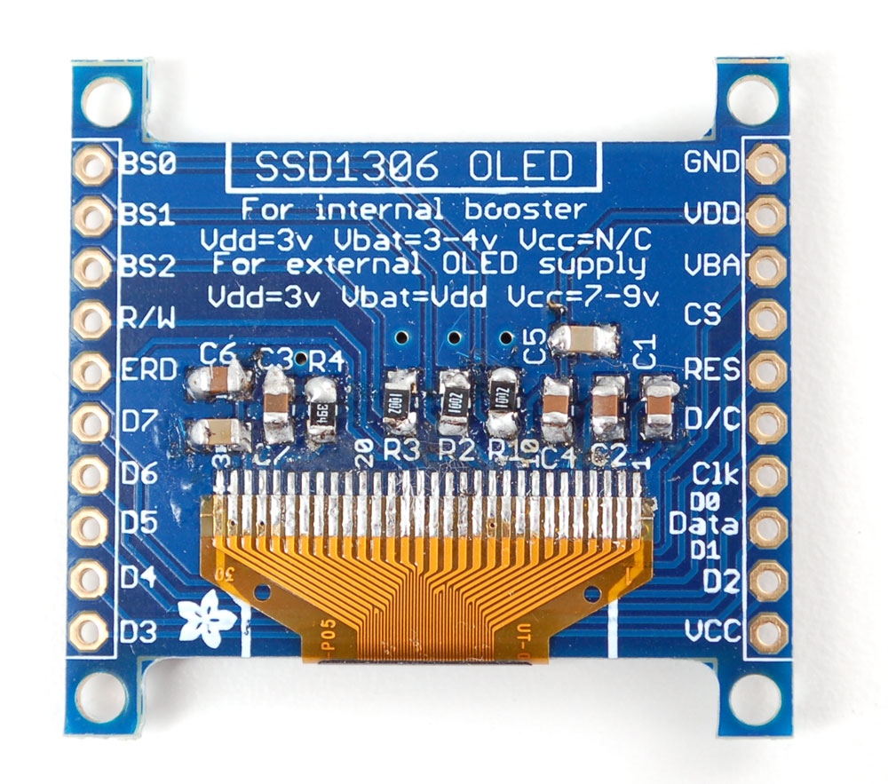
- VDD is the 3.3V logic power. This must be 3 or 3.3V
- VBAT is the input to the charge pump. If you use the charge pump, this must be 3.3V to 4.2V
- VCC is the high voltage OLED pin. If you're using the internal charge pump, this must be left unconnected. If you're not using the charge pump, connect this to a 7-9V DC power supply.
For most users, we suggest connecting VDD and VBAT together to 3.3V and then leaving VCC unconnected
Wiring
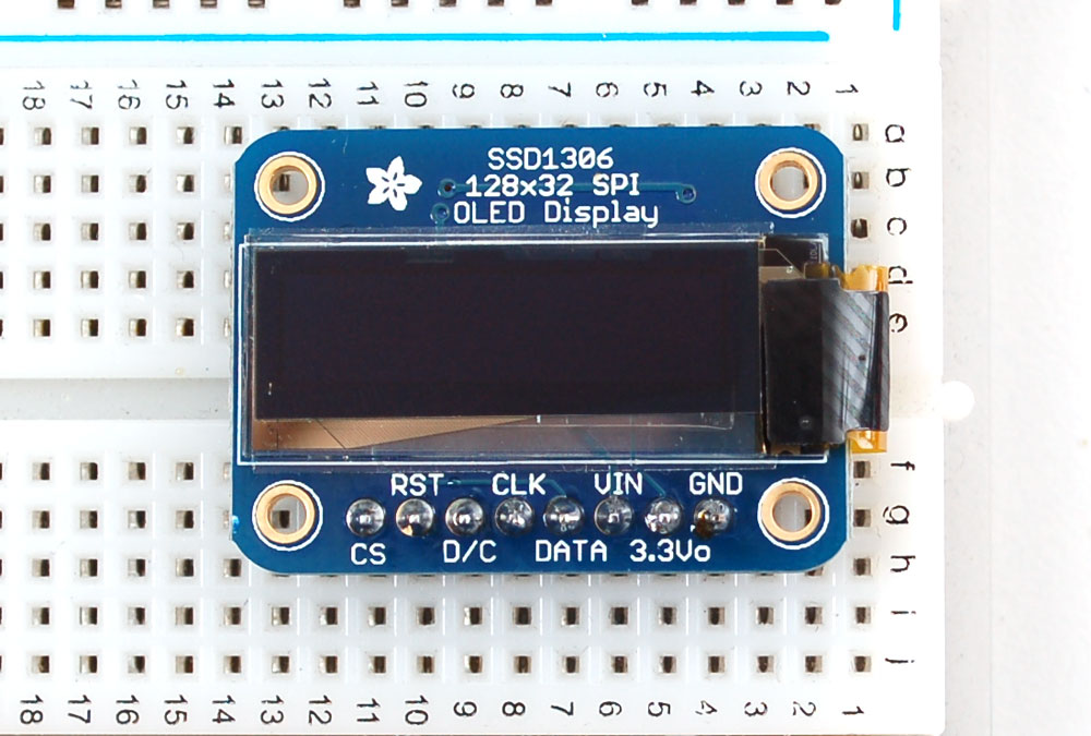
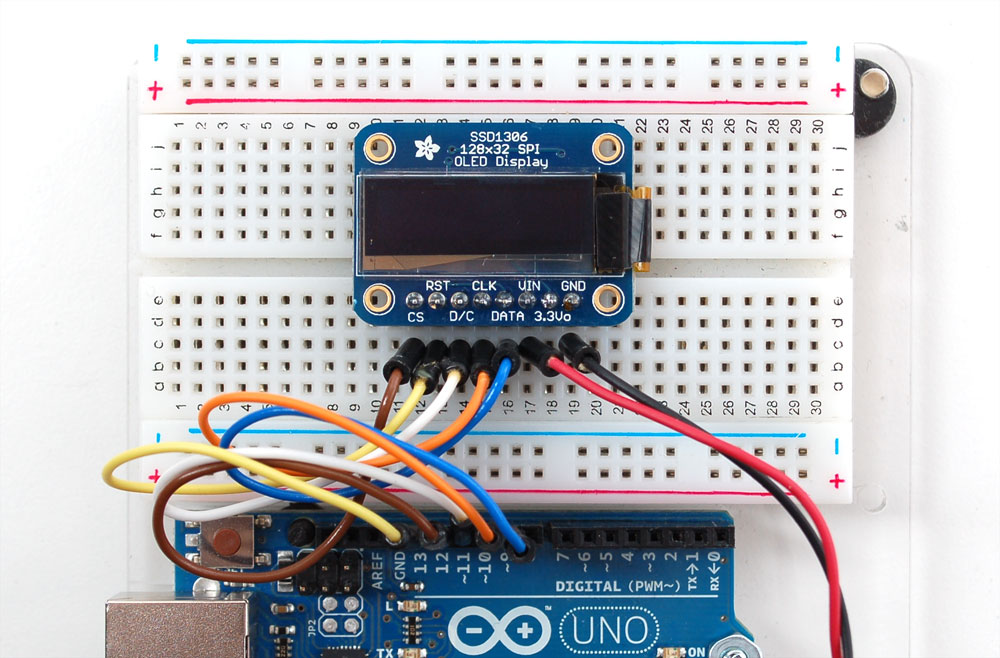
128x32 SPI OLED
The 128x32 SPI OLED is very easy to get up and running because it has built in level shifting. First up, take a piece of 0.1" header 8 pins long
Plug the header long end down into a breadboard and place the OLED on top. Solder the short pins into the OLED PCB
Finally, connect the pins to your Arduino - GND goes to ground, Vin goes to 5V, DATA to digital 9, CLK to digital 10, D/C to digital 11, RST to digital 13 and finally CS to digital 12
If you're using the 128x32 OLED, be sure to uncomment the "#define SSD1306_128_32" in the top of Adafruit_SSD1306.h to change the buffer size
128x64 OLED
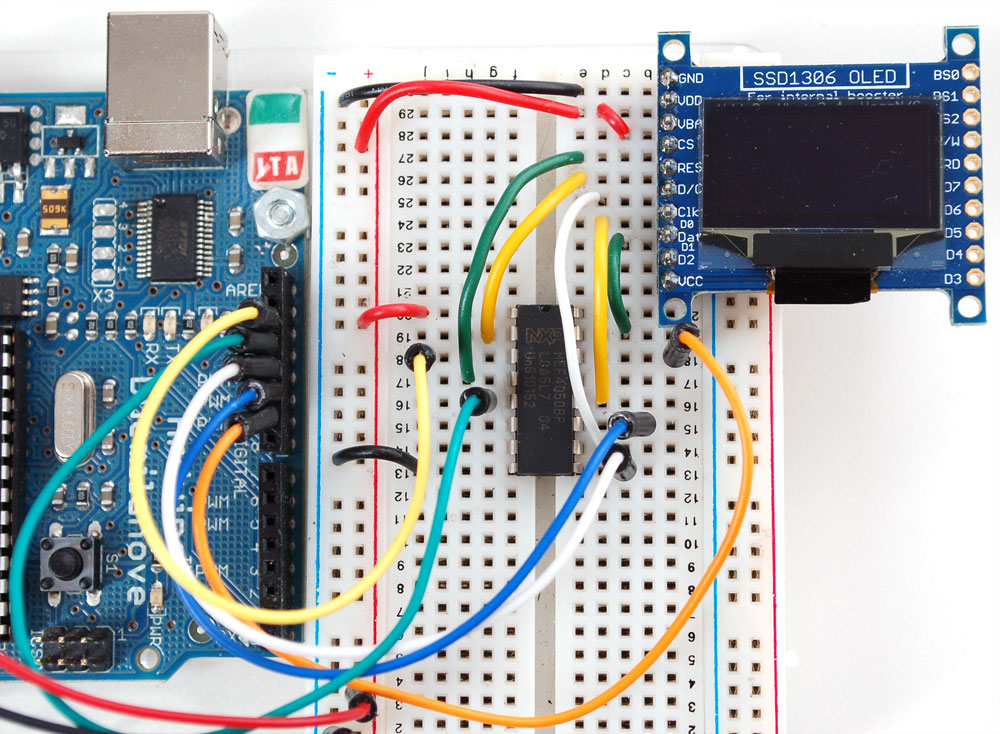
The 128x64 OLED runs at 3.3V and does not have a built in level shifter so you'll need to use a level shifting chip to use with a 5V microcontroller. The following will assume that is the case. If you're running a 3.3V microcontroller system, you can skip the level shifter.
We'll assume you want to use this in a breadboard, take a piece of 0.1" header 10 pins long
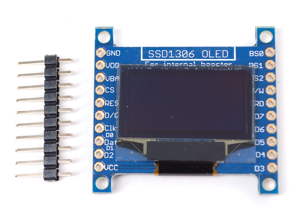
Place the header in a breadboard and then place the left hand side of the OLED on top
And solder the pins

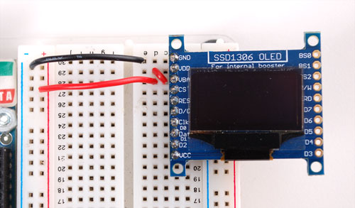
We'll be using the internal charge pump so connect VDD and VBAT together (they will connect to 3.3V). GND goes to ground
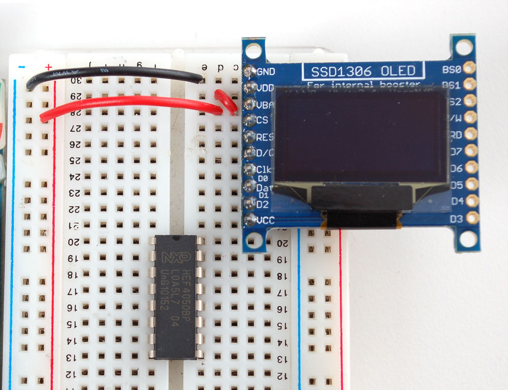
Place a CD4050 level shifter chip so pin one is at the top
Connect pin 10 to D/C pin 12 to CLK (SPI clock) and pin 15 to DAT (SPI data)
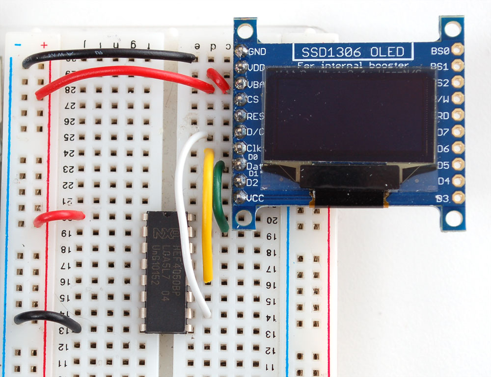
Connect pin 2 to RES (reset) and pin 4 to CS (chip select). Pin 1 goes to 3.3V and pin 8 to ground.
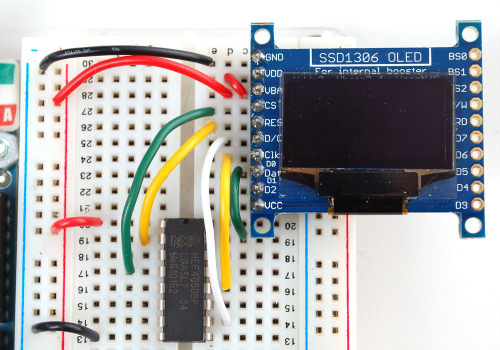
You can connect the inputs of the level shifter to any pins you want but in this case we connected digital I/O 13 to pin 3 of the level shifter, 12 to pin 5, 11 to pin 9, 10 to pin 11 and 9 to pin 14. This matches the example code we have written. Once you get this working, you can try another set of pins.
Arduino Library & Examples
Download and install our Arduino libraries – the links are at the bottom of this page. If you're using a different microcontroller, the code is pretty simple to adapt, the interface we use is basic bit-twiddling SPI.
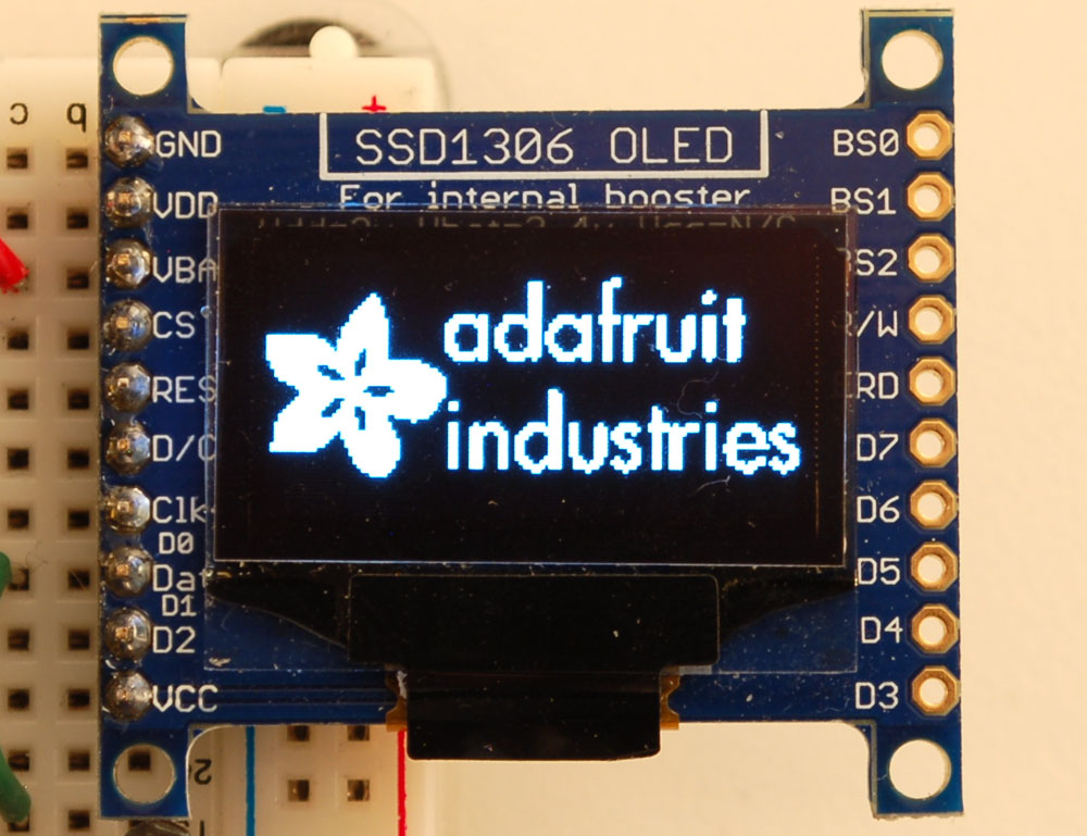
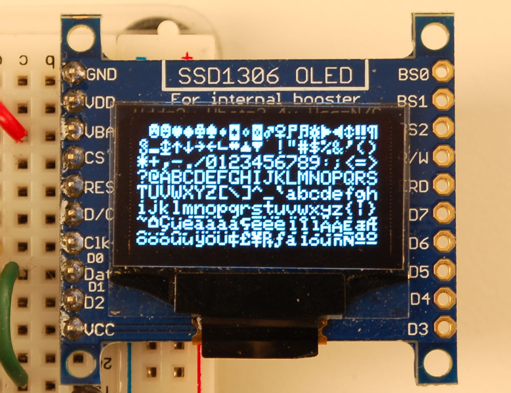
Load the example sketch to demonstrate the capabilities of the library and display.

Create bitmaps
You can create bitmaps to display easily with the LCD assistant software. First make your image using any kind of graphics software such as photoshop or Paint and save as a Monochrome Bitmap (bmp)

Select the following options:

and import your monochrome bitmap image. Save the output to a cpp file

You can use the output directly with our example code

Download
You can download our SSD1306 OLED display Arduino library from github which comes with example code. The library can print text, bitmaps, pixels, rectangles, circles and lines. It uses 1K of RAM since it needs to buffer the entire display but its very fast! The code is simple to adapt to any other microcontroller. You'll also have to install the Adafruit GFX graphics core library at this github repo and install it after you've gotten the OLED driver library.
UG-2864HSWEG01 Datasheet
UG-2864HSWEG01 User Guide
SSD1306 Datasheet
