Table of Contents
LED full color (RGB) Pixels!
RGB Pixels are digitally-controllable lights you can set to any color, or animate. Each pixel contains an RGB LED and a controller chip molded into a 'dot' of silicone, with flanges so they can be pushed into holes in thin sheet material. The dots are waterproof and rugged — they're typically used to make outdoor signs.
Basic stats
- 20mm diameter round waterproof pixels
- Approximately 3 inches (75mm) apart on 4-pin strand
- 5 Volts DC, 60 milliamps max per pixel (all LEDs on, full white)
- LPD6803 LED driver chip provides 15-bit color: Datasheet
- 2-pin SPI-like protocol — easy for Arduino and other microcontrollers
You can pick up RGB pixels in strands of 20 from the Adafruit shop.
Here is a video showing our similar 12mm dots running a test pattern:
Project Ideas
These pixels could be used for stuff like…
LED coffee tables (this one is 'hand made' but you could skip the wiring/drivers part and just use a long strand of our LED pixels now):
A trippy 'light bar':
Signs or displays:
Overview
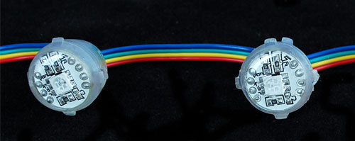
These pixels use a "5050" clear RGB LED and are brighter than our 12mm pixels. The trade off is that they are not diffused, so the color mixing is not as nice; close up, you can see the three separate LEDs. At 5 Volts, they draw a maximum of 60 mA per pixel: 20mA each for red, green and blue.
![]()
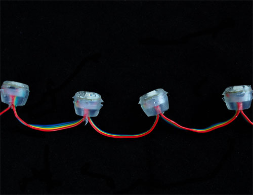
The LED pixels are spaced along a strand of ribbon cable, with about 3 inches or 75mm between pixels. If additional distance is needed you can cut the ribbon cable and solder 4 wires to extend the gap to the desired length.
Powering 20mm Pixels
An important part of running a lot of LEDs is to keep track of power usage. Individual LEDs don't get very hot or use tons of power, but they add up fast!
Each single 20mm RGB LED pixel can draw up to 60mA from a 5V supply. That means a strand of 20 can use up to 1.2 Amps. Of course this is assuming all the LEDs are on. If you keep most of the LEDs off (by color swirling or patterns) the power usage can be 1/3 this or less.
We suggest a nice switching supply for driving LED pixels: either a 5 Volt 2 Amp supply for a strand or two, or our 5 Volt 10 Amp supply for larger installations. For really massive projects, a slightly modified ATX computer power supply can provide 30 Amps to power upwards of 500 pixels!
IMPORTANT: Never, never connect more than 5 Volts to the pixels! This will permanently damage them!
As shown later, connect ground to both your power supply and microcontroller. Then connect the 5V pin to the power supply. A large capacitor (1000uF or so) between 5V and ground is a nice addition to keep ripple down.
Driver Chip
Each pixel contains a small microchip within the silicone dot. The LPD6803 LED driver chip is custom designed for this purpose. These chips are very simple to communicate with — all they do is shift color data in from one pin and out another. To issue data from a microcontroller such as an Arduino, one "shifts out" 16 bits of color information. To write data to 10 LEDs, you would issue 160 bits (10 * 16). Following the data, 32 zero bits will "latch" the data and show the new LED colors.
This chip can handle PWM for controlling color brightness, all it needs is a 'pixel PWM clock' which sets the PWM speed. The faster the clock, the smoother the color…but this signal has to travel all the way down the strand, so it can't be too fast or it'll snag the chips.
An interesting point is that the PWM clock is the same as the data clock. This is nice in that it saves a pin, but does mean that data must be carefully synchronized to the PWM counter in order to avoid unsightly flicker. This is okay but a little annoying because the PWM clock must be continuously issued, and on the Arduino this requires a timer interrupt and costs a fair chunk of CPU performance.
Wiring
The great thing about these pixels is that they're digitally controlled…that is, even though there are only two control lines (data and clock inputs), you can put as many pixels as you'd like in a single long strand, yet each one remains independently controllable.
Though it looks like the 4-conductor ribbon cable is continuous, it isn't! The ground and 5V lines pass through from one pixel to the next, but the two data control lines are different on the input and output sides. The input side goes to the LED driver chip, which then drives its own output to the next pixel in the strand.
When connecting these pixels to a microcontroller, make sure you're connecting to the strand's input pins! Best way to distinguish the correct end is to examine the dots to find an arrow symbol. In the image above, the arrow is in the top right corner. The inputs are on the left and the signal passes to the right, following the direction of the arrow. If connecting multiple strands together, make sure the output of one strand goes to the input of the next.
Wiring is pretty easy since there are only 4 wires. The only important thing is that unless you are sure you will be using only a few of the LEDs at a time, you should not try to power the strip from the 5V on the Arduino. The Arduino is only meant to drive about 500mA of current, and as we saw earlier, a strand can take 1000mA or more if on! For that reason, we suggest powering with an external regulated 5V supply.
Use this diagram with the red wire going to +5V from the power supply, green (serial clock) to Arduino digital pin 3, yellow (serial data) to digital pin 2, and blue to both the ground connection on the power supply and any available GND pin on the Arduino.
Our code can use any two pins, but the examples are written to use pins 2 and 3 as above.
Download
The Arduino library is heavily based off of bliptronics' original code, except we library-ized it and trimmed it down.
To download the library, visit the repository on GitHub.
Click the DOWNLOAD ZIP button near the upper left, extract the archive and then rename the uncompressed folder to LPD6803. Confirm that this folder contains the files LPD6803.cpp and LPD6803.h and the examples folder.
Place the LPD6803 folder inside your Arduino Libraries folder. You may need to create this folder if it does not yet exist. In Windows, this would be (home folder)\My Documents\Arduino\Libraries and for Mac or Linux is (home folder)/Documents/Arduino/Libraries We also have a tutorial on library installation.
After installing the LPD6803 library, restart the Arduino IDE. You should now be able to access the sample code by navigating through menus in this order: File→Sketchbook→Libraries→LPD6803→strandtest
Code!
The code to drive these dots is fairly simple, except that the PWM pin and the data clock pin are shared, meaning you can't just stick the PWM pin on a hardware timer output because then it's not possible to use it for the data clocking. Instead, the library uses an interrupt that goes off every few milliseconds. If there is data to be updated on the strip, it sends that data. If not, it just pulses pin to keep the PWM going.
Note that the interrupt uses Timer 1, meaning the pin 9 and 10 PWM outputs will not work for servos at the same time. If you need this capability, please use a 'software servo' library!
Let's look through the strandtest example code. To use the library in an Arduino sketch, you'll first need to globally declare an LPD6803 object to talk to the strip. It is invoked with three variables: the number of pixels and the data and clock pins:
int dataPin = 2;  // 'yellow' wire
int clockPin = 3; // 'green' wire

// Set the first parameter to the NUMBER of pixels. 20 = 20 pixels in a row
LPD6803 strip = LPD6803(20, dataPin, clockPin);
Next, we initialize the strip in the setup() procedure:
void setup() {
  // The Arduino needs to clock out the data to the pixels
  // this happens in interrupt timer 1, we can change how often
  // to call the interrupt. setting CPUmax to 100 will take nearly all all the
  // time to do the pixel updates and a nicer/faster display,
  // especially with strands of over 100 dots.
  // (Note that the max is 'pessimistic', its probably 10% or 20% less in reality)
  strip.setCPUmax(50);  // start with 50% CPU usage. up this if the strand flickers or is slow

  // Start up the LED counter
  strip.begin();

  // Update the strip, to start they are all 'off'
  strip.show();
}
setCPUmax() configures the Timer 1 interrupt that drives the strand. You can change this from 0 to 100, and it runs in the background. The 'max' is calculated assuming the longest possible timing (when sending data) so its a bit pessimistic. 50% should be plenty, you can mess with this to make the strip more or less 'flickery' You can change this 'on the fly' so for example set it to 0% just before doing a bunch of Ethernet stuff, then back to 50% later.
begin() actually starts the interrupt.
show() refreshes the displayed colors of the LEDs. You'll need to call show() after changing any pixel colors to see this reflected in the LEDs. This way you can change the entire strip at one time (it takes the same amount of time to change one pixel as it does for an entire strip, because the full strip data must be issued regardless).
Last, we'll look at an example function, colorWipe(). This creates a 'chase' sequence that fills the strip up with a color. It is basically a loop that increments through every pixel (which you can query with the numPixels() function) and sets the color of each (incremented with i) to the value passed (c — colors are expressed as a 16-bit variable type, though only the bottom 15 bits are used). The strip output is then updated with show(). Finally there is some delay (otherwise this would happen instantly).
Below that is a helper function that converts a color from separate 5-bit red, green and blue values into a combined 15-bit value (suitable for passing to colorWipe()). The brightness range is from 0 (off) to 31 (max brightness).
// fill the dots one after the other with said color
// good for testing purposes
void colorWipe(uint16_t c, uint8_t wait) {
  int i;

  for (i=0; i < strip.numPixels(); i++) {
      strip.setPixelColor(i, c);
      strip.show();
      delay(wait);
  }
}

/* Helper functions */

// Create a 15 bit color value from R,G,B
unsigned int Color(byte r, byte g, byte b)
{
  //Take the lowest 5 bits of each value and append them end to end
  return( ((unsigned int)g & 0x1F )<<10 | ((unsigned int)b & 0x1F)<<5 | (unsigned int)r & 0x1F);
}
For example, in the loop() function we call colorWipe(Color(31, 0, 0), 50) which will fill the strand with full-brightness red light, pausing about 50 milliseconds between pixels.
  colorWipe(Color(31, 0, 0), 50);  // red fill
  colorWipe(Color(0, 31, 0), 50);  // green fill
  colorWipe(Color(0, 0, 31), 50);  // blue fill
