Table of Contents
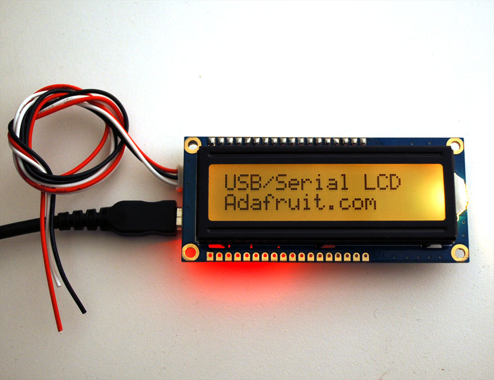
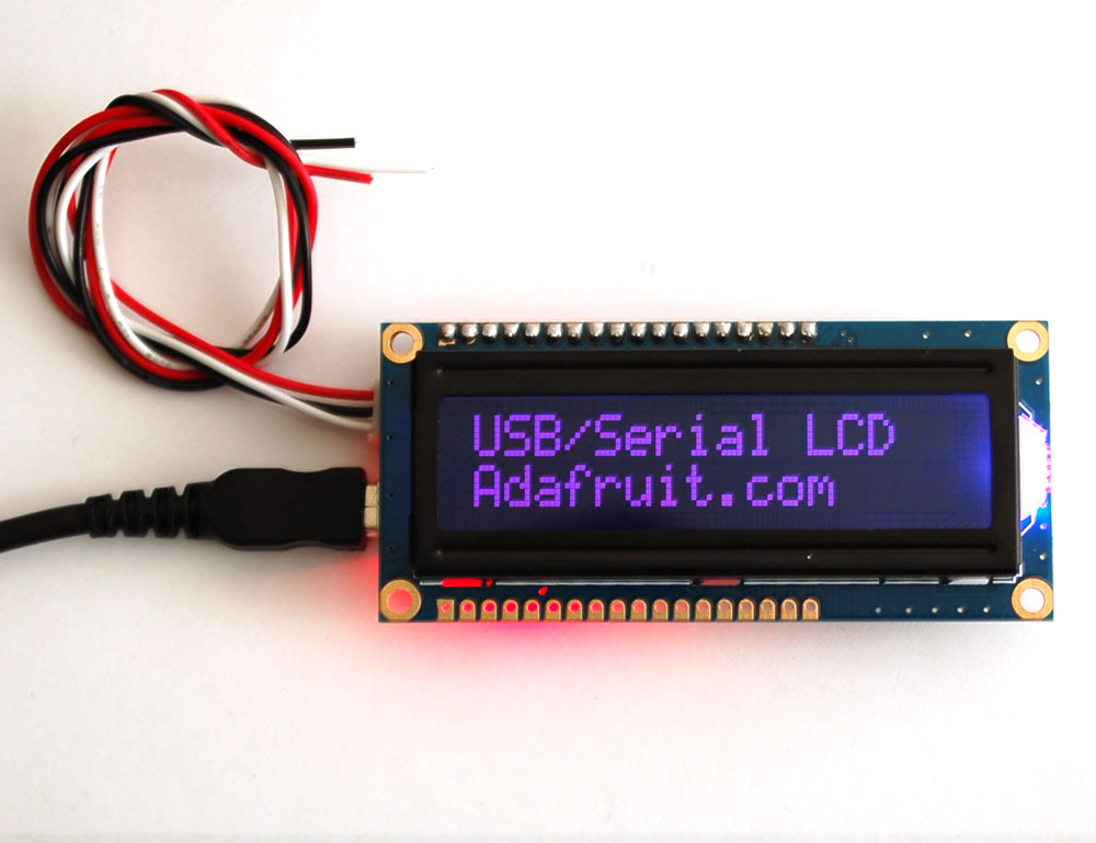
Adding a character display to your project or computer has never been easier with the new Adafruit USB or TTL serial backpack! This custom-designed PCB sits on the back of any 'standard' character LCD (16x2 or 20x4 sized) and does everything you could want: printing text, automatic scrolling, setting the backlight, adjusting contrast, making custom characters, turning on and off the cursor, etc. It can even handle our RGB backlight LCDs with full 8-bit PWM control of the backlight. That means you can change the background color to anything you want - red, green, blue, pink, white, purple yellow, teal, salmon, chartreuse, or just leave it off for a neutral background.
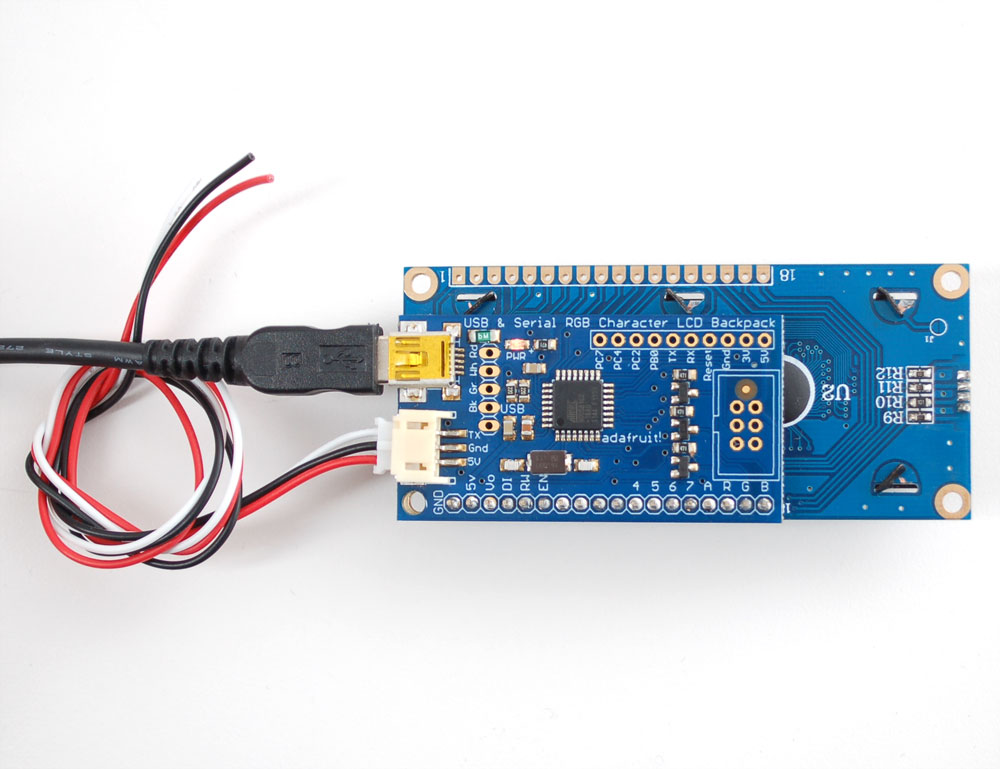
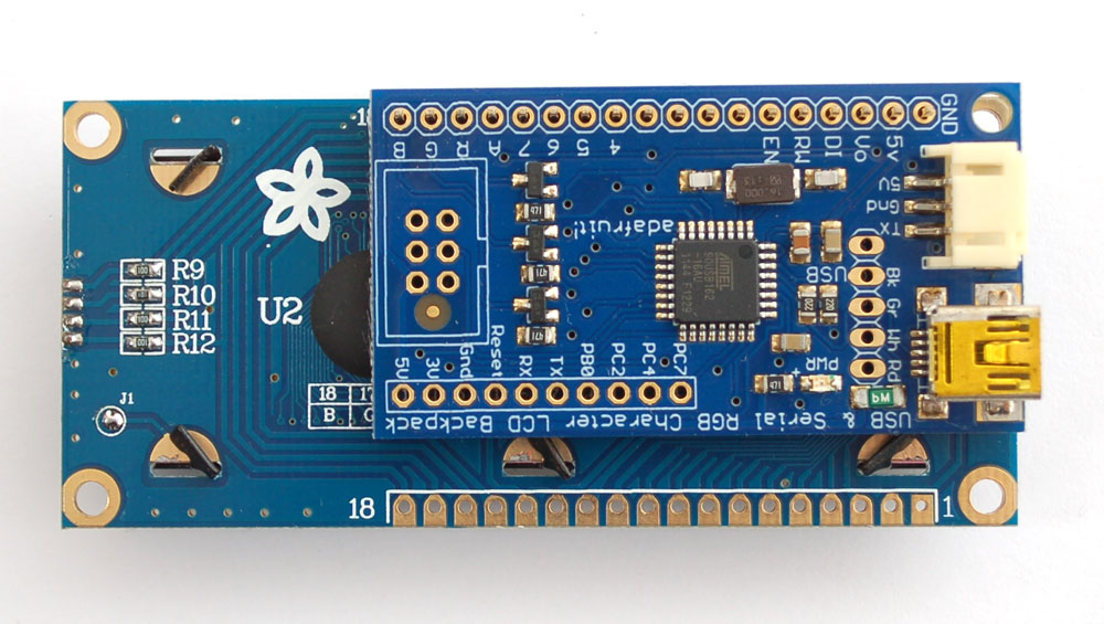
Inside the backpack is an USB-capable AT90USB162 chip that listens for commands both a mini-B USB port and a TTL serial input wire. The USB interface shows up as a COM/serial port on Windows/Mac/Linux. The backpack will automatically select data from whichever input is being used. For the USB connection, it will work at any baud rate. For the TTL connection, the default baud rate is 9600 but you can send it a command to set the baud rate to 2400, 4800, 9600, 19200, 28800, or 57600 baud. (The baud rate is flashed on the LCD during powerup). Any customizations such as baud rate, backlight color, brightness, splash screen, etc. are stored permanently EEPROM.
The command interface is compatible with the popular "Matrix Orbital" specifications so this backpack will work perfectly with computer applications or libraries that are expecting a "Matrix" LCD. We added a few extra commands for the RGB backlight and setting the LCD size. If you don't want to use the commands, you can just start sending ASCII to the LCD and it will magically appear as typed.
USB or TTL Serial
There are two interfaces for transmitting data to the backpack: USB and Serial. USB is the easiest: simply plug a mini-B cable from the backpack to a computer to power and connect. The backpack will appear as a "USB Serial Port" to Windows, Mac and Linux computers. An INF file is required for windows, no driver is required for Mac or Linux. Windows computers will create a COM port, Mac/Linux will create a device under /dev/cu.usbserialXX or similar, run dmesg right after plugging in to see what the device is called. With USB, use any terminal progam to connect at any baud rate to the port and send text and command data. The baud rate is not used for USB so just connect at 9600 or whichever is easiest.
You can also connect with the TTL serial input. This is the red/black/white cable. Power is provided by connecting the black wire to ground and the red wire to +5V. The white cable is the 5V TTL serial input. By default, the backpack is configured for 9600 baud, 8 bit, no parity, 1 stop bit. You can configure the baud rate if you need faster/slower TTL interface. When powered, the backpack will blink the baud rate onto the display for 100 milliseconds so if you're ever really confused, connect while watching the display. You can always connect with USB (baud rate is not used for USB) and reset the baud rate there.
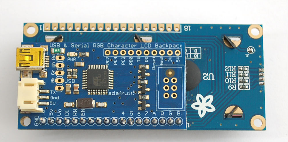
For hard-wiring the USB connection, there is a USB breakout in the standard '5x1' pinout for red, black, white, and green USB wires. For hardwiring the TTL connection, there are breakouts for the RX and TX pin. along the edge of the PCB
Solder on display
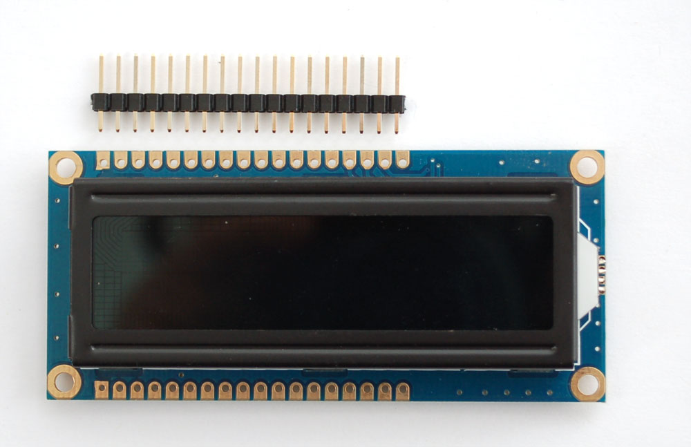
The first step is to solder a character LCD display onto the backpack. Remember that only character type displays are supported, and they can be up to 20x4 in size but no larger. All Adafruit character displays work but we can't guarantee any others will work!
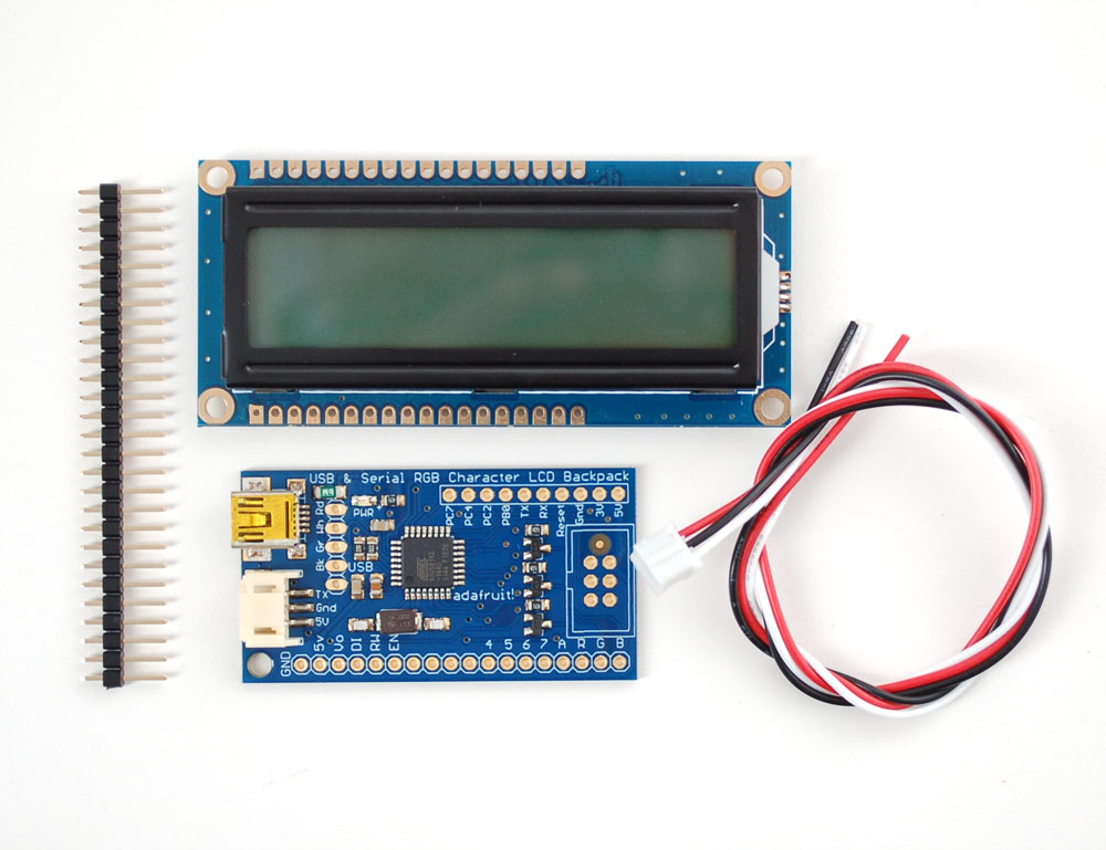
The backpack comes with a piece of header you can use to fit the display on. Its handy to have a solderless breadboard to attach the header on straight. Break off the header so that it matches the number of pins on your LCD
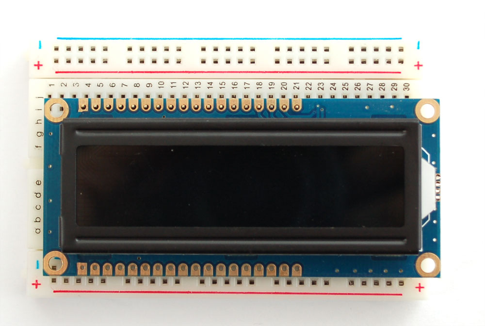
Place the header with the long side down into a breadboard. then place the LCD on top. If you're using an LCD with two rows available, make sure you're using the row that matches the image below.
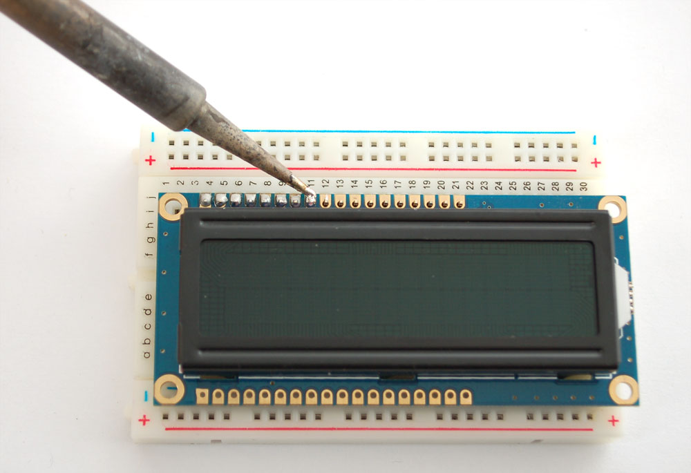
Solder all the headers on with your iron.
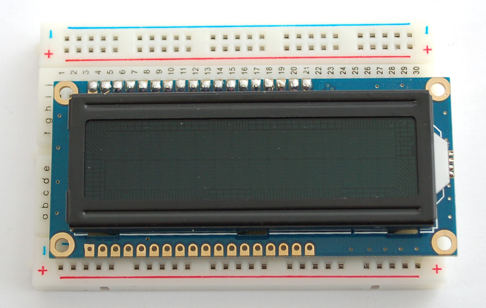
Next, align the backpack so that it matches up with the corner of the LCD, the hole in the backpack should be in the same location
Solder the backpack on completely
Thats it!
Sending text
To display text, just send ASCII characters! There are a few special characters to note:
- New line character (0x0A or '\n') will fill the rest of the current row with spaces (to blank it) and move to the next line
- Carriage return (0x0D or '\r') is not listened to
- Backspace (0x08) will back up the character one space and replace the last character with a space to erase it.
There are also a bunch of special commands, see below for how to send those commands below.
The only character that is 'special' is 0xFE which is the 'command start' character.
Testing with USB
The easiest way to test the LCD and backpack is to connect to it to your computer and send data with a terminal program.
Use any mini-B USB cable to connect to the backpack. If you're using windows, you'll need to point it to an INF driver file. See below in the download section for that INF file. Mac and Linux do not require a driver.
After the backpack is plugged in, it will create a serial port. Under windows this is called a COM port. You can look in the Device Manager→Ports to see what the name of the COM port created is. You should see an entry appear/disappear when connecting the USB cable.

For mac/linux, once you have plugged in the cable, run dmesg to see what the name of the port is, probably something like /dev/cu.usbmodem-XXXX or similar. You can also type ls /dev/cu.* into a Termnal window and see what items appear/disappear when the cable is connected and unplugged.

Now that the port is known, you can use your favorite terminal program to connect. For this example, we'll use the basic terminal built into Arduino. The only downside of the serial port monitor is that you can only send a full string at a time and there's a new line at the end. If you are using a more powerful monitor such as CoolTerm (mac) or RealTerm (Windows) you can watch as each character is entered
Start by selecting the same COM serial port that belongs to the backpack

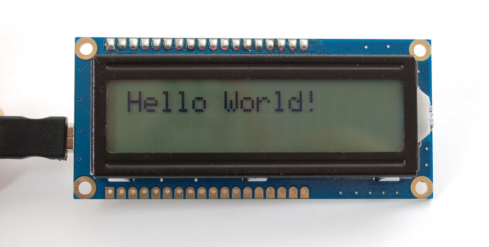
Open the serial port monitor and type Hello World! into the text box

Once you hit Send it will transfer the text to the backpack, and it will appear. Thats it!
Testing with TTL serial
Next we will demonstrate how to send text and commands using an Arduino microcontroller. You can of course use any microcontroller that has a serial output you can configure for 9600 baud. This demo will show how to set the display size, RGB backlight and create a custom character. For more commands, see below for the full list of supported commands
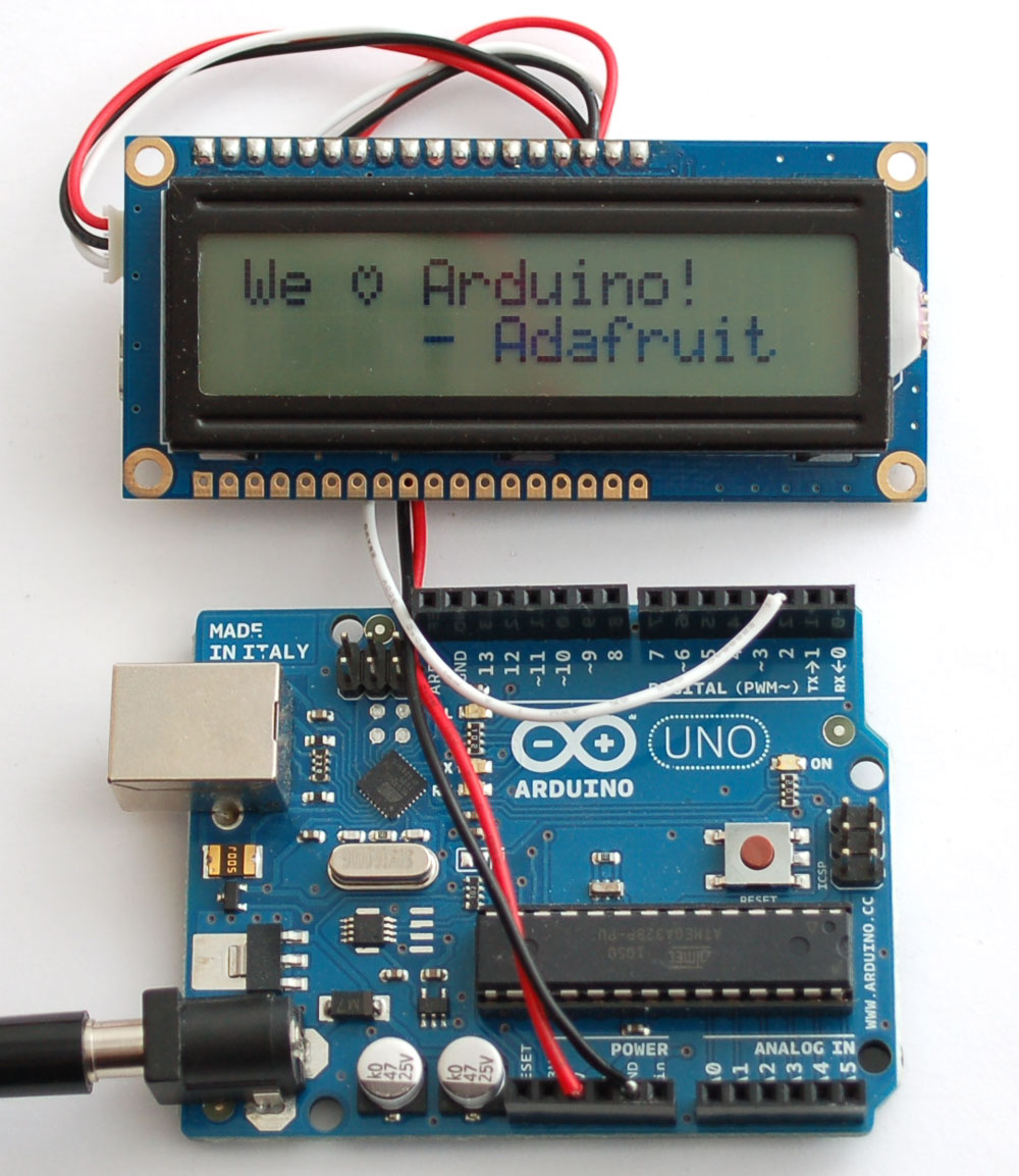
Grab an Arduino and connect the JST cable to the backpack as follows: Red wire goes to +5V, Black wire goes to Ground, White data wire goes to digital #2. You can change the digital pin later, but stick with #2 for this example and adjust later as desired.
You should see the following, with a color-changing background:
Command Reference
The command set is based on the Matrix Orbital specification. We added a few commands to support the RGB backlight and to adjust the size of the display (so one firmware can support 16x2 or 20x4) If you're using software that support Matrix Orbital displays, this backpack should work identically (if not, please let us know!)
All commands start with the special character 0xFE (in hex) which tells the backpack to watch for a special command next.
Basic commands:
- Display On - 0xFE 0x42 <time> - This command turns the display backlight on . The <time> argument is how many minutes to stay on, the command is supported but we don't handle the timeout so that number is ignored
- Display On - 0xFE 0x46 - turn the display backlight off
- Set Brightness - 0xFE 0x99 - set the overall brightness of the backlight (the color component is set separately). Setting is saved to EEPROM
- Set & Save Brightness - 0xFE 0x98 - same as above
- Set Contrast - 0xFE 0x50 <contrast> - set the display contrast. In general, around 180-220 value is what works well. Setting is saved to EEPROM
- Set & Save Contrast - 0xFE 0x91 <contrast> - same as above
- Autoscroll on - 0xFE 0x51 - this will make it so when text is received and there's no more space on the display, the text will automatically 'scroll' so the second line becomes the first line, etc. and new text is always at the bottom of the display
- Autoscroll off - 0xFE 0x52 - this will make it so when text is received and there's no more space on the display, the text will wrap around to start at the top of the display.
- Clear screen - 0xFE 0x58 - this will clear the screen of any text
- Change startup splash screen - 0xFE 0x40 - after sending this command, write up to 32 characters (for 16x2) or up to 80 characters (for 20x4) that will appear as the splash screen during startup. If you don't want a splash screen, write a bunch of spacesMoving and changing the cursor:
- Set cursor position - 0xFE 0x47 <column> <row> - set the position of text entry cursor. Column and row numbering starts with 1 so the first position in the very top left is (1, 1)
- Go home - 0xFE 0x48 - place the cursor at location (1, 1)
- Cursor back - 0xFE 0x4C - move cursor back one space, if at location (1,1) it will 'wrap' to the last position.
- Cursor forward - 0xFE 0x4D - move cursor back one space, if at the last location location it will 'wrap' to the (1,1) position.
- Underline cursor on - 0xFE 0x4A - turn on the underline cursor
- Underline cursor off - 0xFE 0x4B - turn off the underline cursor
- Block cursor on - 0xFE 0x53 - turn on the blinking block cursor
- Block cursor off - 0xFE 0x54 - turn off the blinking block cursor
RGB Backlight and LCD size
- Set RGB Backlight Color - 0xFE 0xD0 <r> <g> <b> - Sets the backlight to the red, green and blue component colors. The values of <rgb> can range from 0 to 255 (one byte). This is saved to EEPROM
- Set LCD size - 0xFE 0xD1 <cols> <rows> - You can configure the backpack to what size display is attached. This is saved to EEPROM so you only have to do it once.Custom Characters
- Create custom character - 0xFE 0x4E <location> <data 8 bytes> - this will create a custom character in spot <location>. <location> can be between 0 and 7 (8 spots). 8 bytes are sent which indicate how the character should appear
- Save custom character to EEPROM bank - 0xFE 0xC1 <bank> <location> <data 8 bytes> - this will save the custom character to EEPROM bank for later use. There are 4 banks and 8 locations per bank.
- Load custom characters from EEPROM bank - 0xFE 0xC0 <bank> - this will load all 8 characters saved to an EEPROM bank into the LCD's memoryGeneral Purpose Output
The general purpose outputs are 4 pins that are not used by the backpack, you can set these pins high or low. GPO1 is labeled PB0, GPO2 is labeled PC2, GPO3 is labeled PC4 and GPO4 is PC7
- GPO Off - 0xFE 0x56 <num> - set the general purpose pin <num> to LOW (0V)
- GPO On - 0xFE 0x56 <num> - set the general purpose pin <num> to HIGH (5V)
- GPO Start State - 0xFE 0xC3 <num> - sets the 'initial' stae of the GPO pin <num>Not handled!
- Set auto-line-wrap on - 0xFE 0x43- and Set auto-line-wrap off - 0xFE 0x43- are not supported. We found that having auto-line wrap off was just not very useful so its automatically on all the time.
- Initialize/Place Medium & Large Numbers, Horizontal bar and vertical bar -this is not supported
Download
- Firmware and USB testing software @ github
- LCD Smartie - a popular character LCD driving program
