Table of Contents
An “Internet of Things” Camera
Simple remote monitoring using a first-generation Eye-Fi wireless SD card and Adafruit Data Logging Shield for Arduino
Introduction
The Eye-Fi card is a tiny wireless memory card. It stores photos and fits inside a camera just like a regular SD card, but also has built-in WiFi transceiver that can upload images to your computer, smartphone or to various photo-sharing sites. We use one here when taking pictures for our tutorials — it’s a great timesaver, eliminating the extra USB transfer step that’s otherwise necessary.
Can the Eye-Fi card work in an Arduino SD card adapter? You bet! Adding a TTL Serial JPEG camera, together with some minimal prep work, we can then create a self-contained wireless monitoring camera with motion-sensing capabilities. Hide it inside a hollowed-out book or a plush dinosaur toy and discover who’s been eating all your Thin Mints cookies!
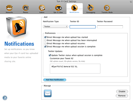
What makes this combination way cooler than just a normal SD card or a USB cable to a computer is all the infrastructure provided by the Eye-Fi service — not just transferring images to your computer, but pushing them to your smartphone, photo-sharing sites like Flickr, issuing email or Twitter notifications, etc. This is all configured through the Eye-Fi application — there’s no additional coding required.
The camera project didn’t require any major engineering effort, but rather was a simple “mash up” of existing elements — a perfect example of the sketching principle of Arduino. Being Arduino-based, it’s also easy to tweak…say if you’d like a time-lapse camera rather than motion sensing, or to hack in sensors such as a laser “trip wire.” Let’s see how it’s put together!
Parts and Software Lists
Parts used in this project include:
- Arduino Uno (or compatible) microcontroller board; anything with standard shield spacing and a 328P processor (the Arduino Mega won’t work).
- TTL Serial JPEG Camera (either the bare board or weatherproof version)
- Shield Stacking Headers for Arduino make it easier to change the wiring around as needed
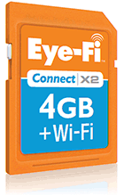
- Eye-Fi wireless SD card (any model).
- A suitable power supply: either a 9V 1A wall adapter…or, for standalone wireless use, our 6-cell AA battery holder is best. For the smallest possible package, a MintyBoost can also work, but provides only about two hours’ run time.
- The usual electronic project bits and bobs: wire, soldering tools, etc.
Links to software:
- Eye-Fi sketch for Arduino (required)
- VC0706 Serial Camera Library (required)
- Realtime Clock Library (required)
- Eye-Fi Center configuration software for PC and Mac (not Adafruit code — please contact Eye-Fi tech support for any help or issues with this software)
Make It!
Before getting into the full wireless project, you might want to work through the TTL Serial Camera Tutorial and try the example sketches included with the VC0706 serial camera library. Once that’s working, the camera setup is easily adapted to this new task.
The aforementioned tutorials place the camera on Arduino pins 2 and 3 in conjunction with the SoftwareSerial library, keeping the Arduino’s native serial port available for communicating to a host computer. But the sketch used here instead assigns the camera to the hardware serial port for added robustness. Devices have their own independent clock sources, and baud rates always have a bit of slop…sometimes they fall out of phase and a glitch occurs, as can happen between the camera and Arduino. The hardware serial port is less prone to these errors. Not 100%, but noticeably more resiliant than SoftwareSerial in this regard. Maybe 1 in 100 images arrive corrupted, vs. about 10x that rate with SoftwareSerial.
But using the Arduino’s serial port for the camera prevents us from sending debugging and status messages over USB. Instead, the LEDs on the Data Logging Shield are used…various blink patterns indicate the current status. Using the serial port also requires that the camera be unplugged when uploading sketches to the board, since it would interfere with the serial transfer.
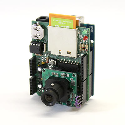
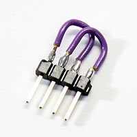
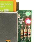
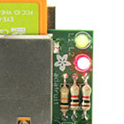
The Data Logging Shield includes extra soldering vias adjacent to each Arduino pin. The serial camera is connected to the vias for pins 2 and 3 (pin 3 to the camera needs to pass through a voltage divider using two 10K resistors, as explained in the TTL Serial Camera Tutorial…this fits neatly in the prototyping area on the Data Logging Shield), and then two short jumpers were installed into the pass-through headers: pin 0 to pin 2, and pin 1 to pin 3. Removing the jumpers allows sketches to be uploaded to the board and the original camera examples can be run unmodified…then install the jumpers to let the special EyeFi sketch run. I put these jumpers on a strip header to make it easy to reconfigure:
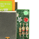
Pins 5 and 6 are then connected to the red and green LEDs on the Data Logging Shield. The finished setup resembles the following (with solder connections between adjacent components being made on the back of the board):
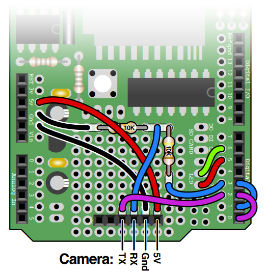
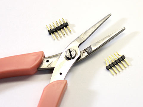
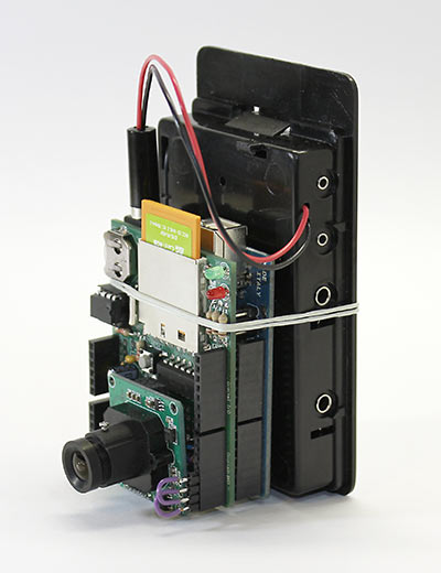
The camera can be connected to the board with a bit of ribbon cable, allowing some freedom to fit the project into different enclosures or conceal it within some discreet object on a shelf. As I’m fond of compact, self-contained things (like bento boxes!), I instead chose to nestle the camera right over the shield. The camera board is just a tad larger than the prototyping area, but if you don’t install the 6-pin ISP header on the shield, then there’s just enough space to tuck it in there. The 2mm pin spacing on the camera can be adapted to a 0.1" header using extra-long male pin headers and needlenose pliers.
The simplest way to power this is with a 9 Volt wall adapter. But if you need something entirely cordless and self-contained, a 6-cell AA battery pack should run it for several hours, or with a USB cable and MintyBoost you can get about 2 hours run time. Unfortunately a 9 volt “square” battery just can’t supply enough current for very long.
Before proceeding any further, back up any data you might currently have on your Eye-Fi card. Just in case there’s some bug that’s been overlooked in the sketch, I’d hate to be the one to clobber your priceless irreplaceable wedding photos. So please, PLEASE back that up first!
The Data Logging Shield requires that the card be properly formatted. Some cameras and operating systems use a bit of “artistic license” when formatting SD cards, and the shield can’t always read or write these. You might need to borrow a friend’s more recent digital camera to format the card. Recent versions of both Mac OS X and Windows 7 seem to handle this better as well; with the latter, select FAT32 with a 32K allocation block size when formatting.
With the card connected to your computer though a USB reader, you can then use an application downloaded from the Eye-Fi web site to configure it for access to your wireless network and select various settings for how and where you want images transferred. Once configured, if you have a digital camera, test it with that first. When the digital camera setup is known working and images are being transferred as expected, you can erase the images on the card and move it over to the Data Logging Shield.
If you haven’t set the real time clock on the Data Logging Shield, do that first. Remove the jumpers between pins 0-2 and 1-3, then load the ds1307 sketch from the RTClib examples. Uploading this to the board will set the clock, which is then maintained even with power disconnected.
Next, upload the EyeFi sketch, then re-install the jumpers between pins 0-2 and 1-3. You can then either press the reset button to start the sketch, or disconnect from the computer and attach a power adapter or battery.
If using the latest Eye-Fi “X2” cards, you'll need to enable this one extra line in the sketch (it’s commented out by default)…around line 122:
SD.enableCRC(true);
Use It!
 When power is first connected, the green LED on the Data Logging Shield should turn on, indicating that the board has power and the sketch is running. If the sketch encounters an error during this initialization phase, the green LED will turn off and the red LED will flash to indicate the problem:
 | Very fast flash: clock initialization error. Did you run the ds1307 sketch to set the time? Is the clock chip correctly installed in its socket, and the backup battery installed with the correct polarity? |
 | Fast flash: SD card initialization error. Is the card properly seated in the SD socket? Did you format it using the SdFormatter sketch before use? |
 | Slow flash: Camera initialization error. Did you re-install the jumpers from pins 0 to 2 and 1 to 3? Is the other wiring (5V, ground, TX, RX and the voltage divider) correctly laid out? |
 | Solid red: Could not create the folder for writing images. Is the filesystem write-protected? |

After successful startup, the green LED will slowly pulse a la sleeping Mac. When motion is detected, the green LED will turn on steady, the sketch pauses for a moment (the motion detection is quite sensitive and sometimes triggers before anything interesting is fully in-frame), then captures a 640x480 pixel image and writes it to the SD card as a JPEG file. The red LED is again used in this stage to indicate errors:
 | Red + green LEDs both ON for 5 seconds: failed to take picture (perhaps a serial communication error with the camera). |
| Red LED alone ON for 5 seconds: couldn’t open file for output on SD card. Card or directory might be full or write-protected, or the card has jostled in the socket. |
If running on battery power, as the voltage drops toward the end of the charge you’ll start to see either or both of these errors with increasing frequency.
When an image is successfully captured and the output file is opened, the green LED will then blink while the image is written to the card. This may take about 10-15 seconds.

The process then repeats, returning to the pulsing green LED and watching for motion.
Provided the card and Eye-Fi services are properly configured, and provided the card is within range of your wireless access point, as images are captured and written to the card they’ll then be sent to the Eye-Fi server and in turn forwarded to your computer, smartphone, etc. — however you’ve configured it. This is all explained (and supported, thanks) on the Eye-Fi web site. They have apps for iPhone and Android, as well as Windows and Mac on the desktop.
How It Works
The sketch relies on a couple of tricks in order to work with Eye-Fi: First, you can’t just dump any old file anywhere on the card and expect it to work — it’s not a big truck! The sketch needs to simulate the same directory hierarchy as one of the supported cameras…in this case, it acts like a Canon camera, and images will be placed in the directory DCIM/CANON999. Second, the card will only transfer JPEG files that are 20K or larger. The 640x480 images used by the sketch are usually well over this limit, but if you change the program’s settings to use one of the smaller image sizes, the sketch will pad out the file if needed to this minimum size (any well-written JPEG viewer will disregard this extra data). I had some reservations about gaming the system this way, but the fact is that a few 20K images a day will be far less taxing on the Eye-Fi servers than the typical 12+ megapixel images to which it’s regularly subjected.
So there you have it. What uses can you come up with? Is the mail here yet? Who’s sneaking in through the cat flap and eating all the kibble? Does the refrigerator light really turn off when the door is closed?
Play It Safe
Before you go running off with reckless abandon, and while these are probably obvious, there are a few points that need to be made for posterity:
- Do not use this as a medical monitor. This is not a medical-grade device.
- Do not use this as a security camera. This is not a security-grade device.
- Follow the law. Covert surveillance is illegal in some places and settings.
- Don’t abuse the Eye-Fi servers. The “free” lifetime bandwidth (for non-premium services) is reflected in the price we all pay up-front.
