The SpokePOV software allows you to easily upload, download, verify, manipulate, fold, spindle, etc. your SpokePOVs! The software is written in wxPython C++ and is available as a Windows / MacOS X executable.
For windows users: download the zip file and uncompress it somewhere convenient. If you are using the parallel port, download and run/install giveio (from the Download page) to let the software talk to the parallel port.
For Linux, FreeBSD, etc. users: download the SpokePOV.py file. Make sure you have Python 2.4 installed. Also install wxPython & pyParallel and any other dependancies that those modules require. Have fun!
For MacOS X download the SpokePOV dmg and copy the application to somewhere convenient.
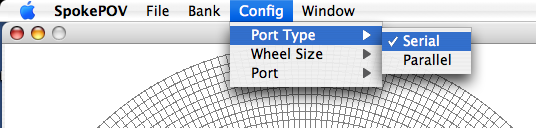
First select serial or parallel (on Mac, you can only choose serial)
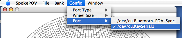
Next select which port to use.
Important Note: under MacOS X sometimes there are multiple names for one port (/dev/cu.KeySerial1 and /dev/cu.USA19H1b1P1.1 for example. Try both! I've found they act differently and get better reliability with some over others!
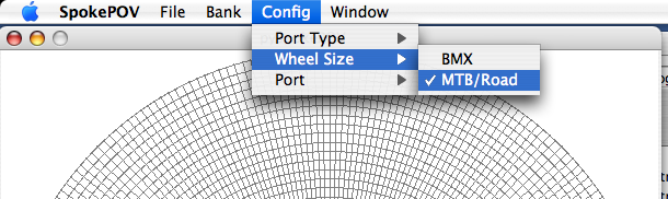
Select what size wheel you're using
The configuration should be saved so you only have to do this once.
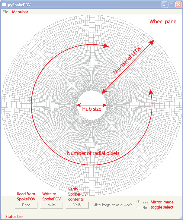
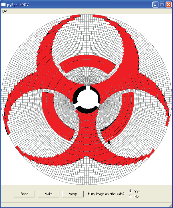
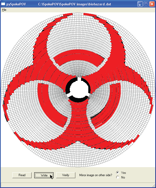
Once you connect, you can see the graphical interface for editing what image will be displayed. The wheel panel shows a simulated image of what is in the SpokePOV. When you start up, and connect, its empty. You can click (and drag) in this window to 'draw' pixels. This is a very slow process as the software isnt very fast, its better to import a bitmap (.bmp file) from a different program and then edit it. The wheel panel has one square for every pixel of resolution. If you're using this with a BMX configuration, the wheel will have fewer LEDs so it will appear a little different. The empty spot in the middle corresponds to the hub size, the space where no image appears.
The main controls for the SpokePOV are in a panel below the wheel panel. The three buttons are used to 1) write the image currently in the wheel panel to the connected SpokePOV 2) read the image currently in the connected SpokePOV into the wheel panel and 3) verify that whats in the wheel panel is also whats in the SpokePOV.
There is also a toggle for mirroring the image. Since SpokePOV is double sided, you can have the image on the opposite side either be mirrored (so that it looks backwards on the opposite side) or not (so it appears exactly the same on both sides). For example, if you have text you want to display, the image should not be mirrored. However, if you want an arrow that points in the direction you're biking, then you want it to be mirrored.
At the bottom of the window is the status bar which will tell you details about whats going on or any errors that have occured.
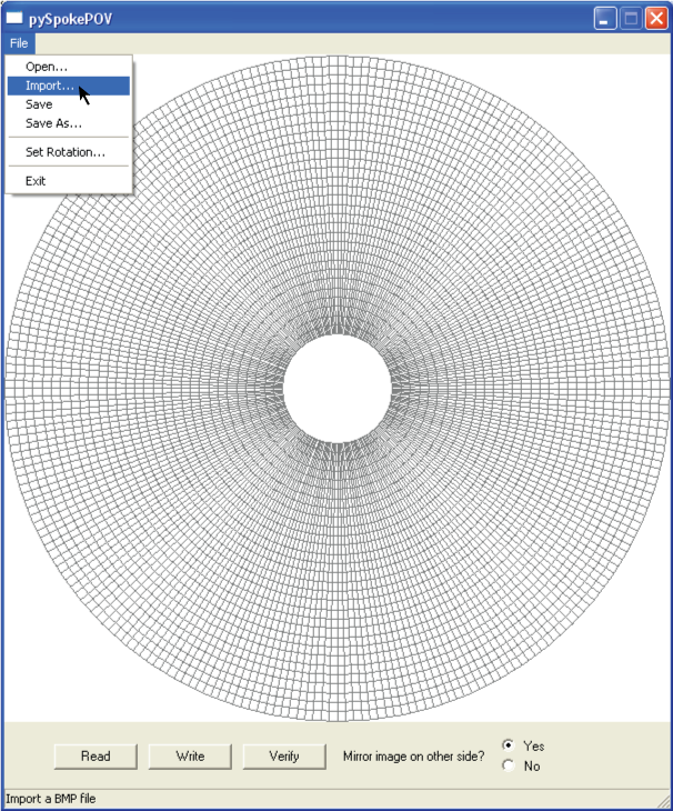
First think you probably want to do is import a bitmap image. There is a bitmap of a biohazard distributed in the zip file. Bitmaps must be monochrome or at least grayscale. The software assumes that 'white' pixels means no LED should be on and any other color means a pixel. You'll get best performance if your bitmap is at least 600x600 pixels large. When you import a bitmap, the software will automatically figure out what the image should look like. The imported image will appear in the background, the red lines show where the LEDs will be lit.
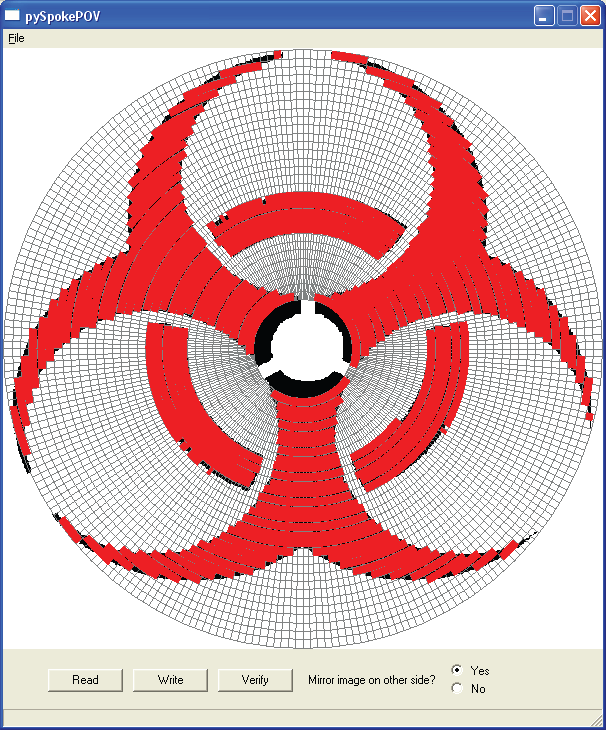
The software tries to figure out what the image should look like, but as seen above, the bitmap isnt aligned perfectly. To touch up the image, click on pixels (or click and drag to draw & erase).
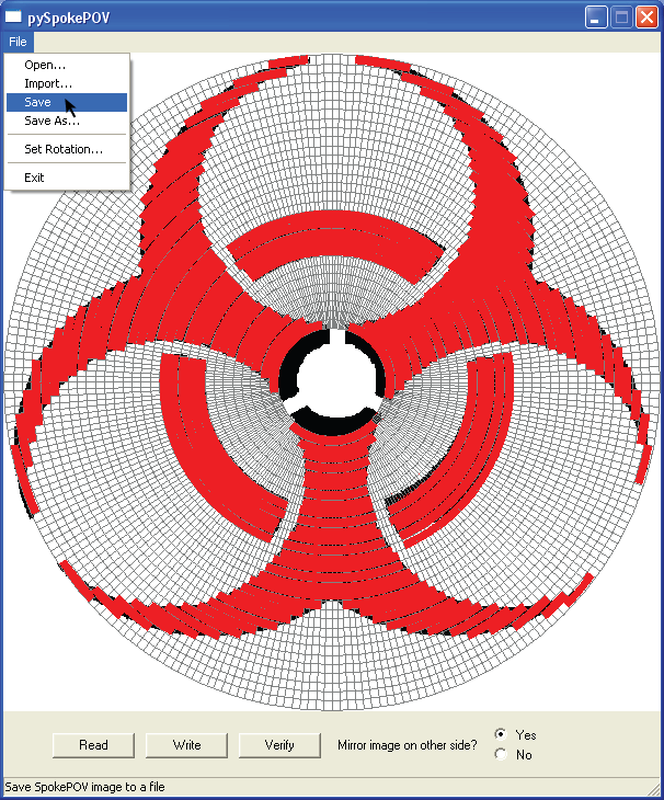
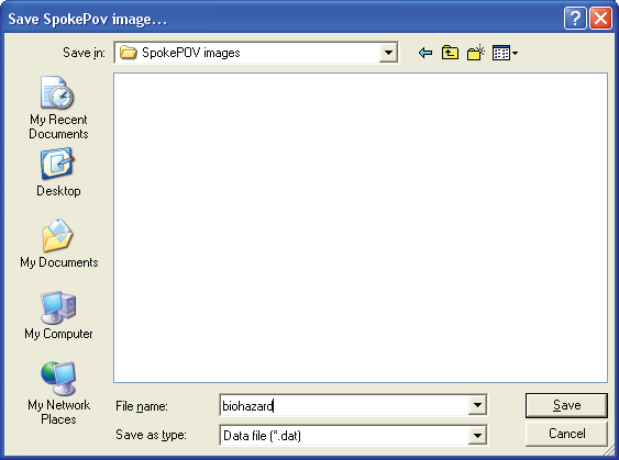
Now that you've done some edits, it might be good to save the image data file for later.
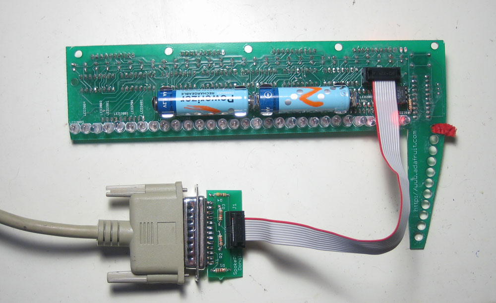
Now its time to write the image data to your SpokePOV. Connect the dongle to your computer parallel port. and plug the programming cable into the SpokePOV. Press the reset button to make sure the SpokePOV is ready for upload. Some people say they have to do both a hard reset (flick one of the battery contacts to disconnect power briefly). Whichever works!
Now click on the write button.
If all is well, the status bar will show the address incrementing and the LEDs on the SpokePOV will blink to show the progress. Sometimes the program stops redrawing. In this case the program will look like its 'hung' or 'stalled'. Chances are its just not redrawing. Wait a full minute before assuming the program has actually crashed and look to see if the SpokePOV LEDs are not scrolling, which would indicate a crash. There are 1024 addresses, it should take 30-60s to write a full image. If you are using a USB/serial converter it may be longer...
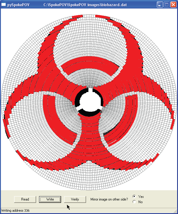
When the image is done uploading, the status bar will display the elapsed time.
![]()
If something goes wrong in the middle of writing the image, you'll get an IO ERROR message. Usually this occurs if you unplug the cable or turn off the SpokePOV, etc. Just press the reset button and try again.
![]()
If the error is at address 0, that means it couldnt even start. This could be due to a bunch of different things, like you didnt run giveio.bat, or maybe something isnt plugged in, or you soldered the dongle or the spokePOV headers incorrectly, or the SpokePOV wasnt reset before you started writing, or the microcontroller is programmed incorrectly, etc. If you've successfully writen to the SpokePOV before, check your connections, try resetting the hardware and try again. Otherwise, check your soldering too.
![]()
One more thing to do is set the rotation variable in the SpokePOV. You have to do this the first time you use the SpokePOV and then again every time you move where the magnet is located or if you move the SpokePOV to a different wheel. Basically, this variable tells the SpokePOV where the magnet is located so that when it draws out the image it will appear 'right side up'! You may want to reset the board before you do this just to make sure its ready for programming.
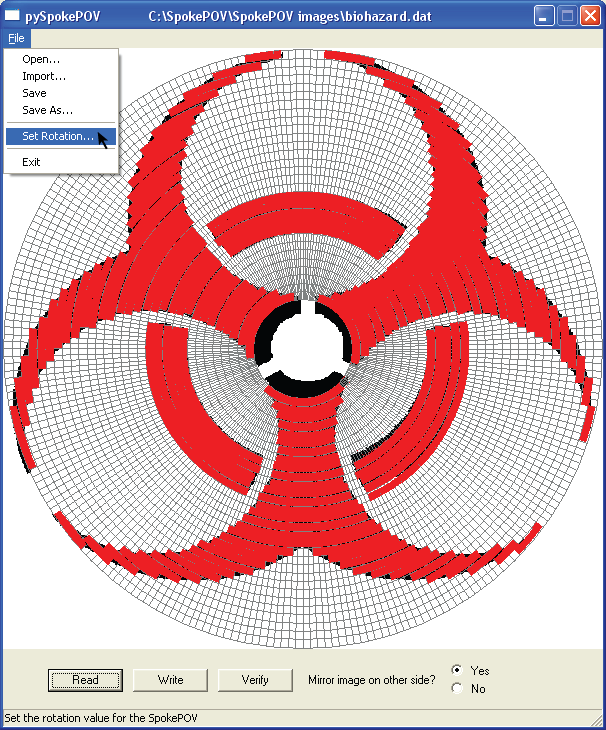
When the menu is selected, the software will read the current value from the connected SpokePOV. To write a new value, edit the number and click Write. When you're done, click Done. The rotation offset should be between 0 to 255. The exact value you want to use will depend a little on your bike geometry. Assuming you mount the SpokePOV so that the magnet is on the right side (your right side, if you are on the bike) here are some rough numbers you can start with and then tune from there. Here is a diagram of where these frame parts are located.
| Location | Value |
| Fork | 220 |
| Chainstay | 64 |
| Seatstay | 32 |
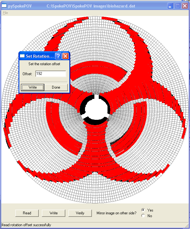
If the SpokePOV isnt reset, or connected correctly, the dialog box wont pop up and you'll get an IO ERROR. Debug this the same way you would if it was a writing error.
![]()
Your SpokePOV is ready to go!
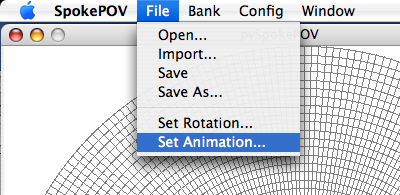
I'll add pictures later but here is a basic description of the animation system (which was a clumsy hack but everyone seems to want :)
- The images are stored in the 25Cxx EEPROM, the other variables are stored in the microcontroller.
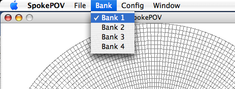
- Each image takes 32 bits (4 bytes) x 256 = 1024 bytes = 1Kbyte of storage. Therefore a 1K EEPROM (25C08) will store one image, a 2K EEPROM (25C16) will store two and a (25C32) will store four. You can select which bank you want to upload to from the Bank menu.
Note that the software cant tell how many banks you have so it assumes 4. If you have only 1K of storage then each bank is the same (so just use Bank 1)
- The firmware in the microcontroller automatically goes through the EEPROM showing each image, without knowing how large the EEPRORM is. Therefore, you can swap out a different EEPROM at any time you want
- This also means that you have to fill all the banks with something. You cant just upload an image to the first bank and nothing to the other three, or the spokepov will display 'nothing' for 3 out of the 4 animation cycles
- Animation timing is defined by cycles/rotations, not seconds. I usually set this to 10-20. You can set it via the menu item.
- You can sync all the spokepovs by quickly resetting them before you start.
- Animation doesnt work great, but it does work. One way to improve it may be (assuming you have more than one spokepov) to leave out the hall effect sensor on all but one and wire the ground and sense wire (but not the VCC power wire) all together so that they are forced to sync together. You'll have to mess with the offset value though.