
Kite aerial photography (KAP) is a fun hobby for
engineers and artists alike: building the kite and rigging can be
a substantial endeavour, and the resulting images can be beautiful.
However, one unlucky gust can send your camera crashing to the ground
(see the KiteCam Disaster
Fund website for tragic videos.)
The easiest way to start taking aerial photos is to rig a manual
or digital camera using a stabilizing harness to the kite lines,
then use a timer to trigger the camera to take a picture. On this
page I describe how to use a simple timer circuit to trigger disposable
digital cameras, now available in many drug stores, to take a picture
once a minute after a 3 minute delay.
Disposable cameras are a good choice for beginner
KAP enthusiasts. Their low cost ($5-$10) means that there's no big
loss they crash to the ground. Most are pre-focused to infinity
which means they're good for taking scenery shots. They are also
lightweight, with plastic bodies and small plastic lenses.
Disposable manual cameras (with 35mm film) have been around for
a while, and there are many low-cost rigs people have designed that
use them. Unfortunately, low-cost film cameras require winding between
shots, so you can only take one picture per launch. Digital cameras
are therefore much preferable, and now there are low-cost and even
'disposable' versions. Digital cameras also use electronic (as opposed
to manual) switches, which means you dont need a jig & servo/cam/relay/solenoid/actuator/etc
to trigger the shutter.
If you end up liking KAP and feel comfortable with your kite-handling
skills, you might want to invest in a higher-end digital or automatic-winding
35mm SLR camera. In the long run it'll be cheaper because you don't
have to buy a new camera every time and if you get a digital camera
you don't have to pay development cost. With a little effort you
can even reuse this circuit to trigger your new camera.
There are at least 4 disposable digital cameras: the 'original' Dakota, the Walgreens version, and the new 'PV2' Dakotas (red and blue). The first two are no longer manufactured, and you probably won't be able to buy them anywhere. The new Dakotas recently came out and are sold at CVS, Ritz Camera, Wolf Camera, and probably some other camera shops. Since these are the most available I'll use the more inexpensive of the two ($10, without color LCD) for demonstration.
The new Dakota digital disposables weigh 4.5oz, come with 2 high quality alkaline batteries and take 25 pictures. I believe the CMOS sensors are 2MP but theres a good chance they're more like 1.5MP. The $20 version comes with a color LCD to preview pictures, the $10 version has a simple LCD that displays how many pictures are left. I don't see much point in buying one with a preview screen if you're going to attach it to a kite, but I assume the insides are identical.
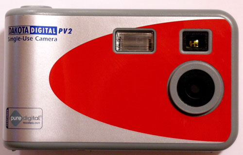
The 'new' Dakota. The red one has a color LCD, the blue one doesn't and is less expensive.
Cameras are really not the best form of consumer electronics to take apart, they're often pretty delicate and the flash circuitry is at high voltage. Disassemble and modify at your own risk!
Materials needed:
Disposable camera, soldering iron and solder, large flathead screwdriver, precision phillips screwdriver, needlenose pliers, angle cutters, 'helping hands' or mini vise, wire, tape.
Breadboard and/or prototyping board, CMOS 555 timer chip, 47uF capacitor, 470uF capacitor, 3x 680K resistors, 1K resistor, switching diode (1N914 or 1N4148), red LED, small toggle or slide switch.
- Disassemble the camera:
Take the camera out of the packaging, take out the batteries, remove the 3 screws that hold the body together. Take off the back cover, being careful not to touch any of the electronics on the inside (they may be at high voltage), and put the plastic case aside.
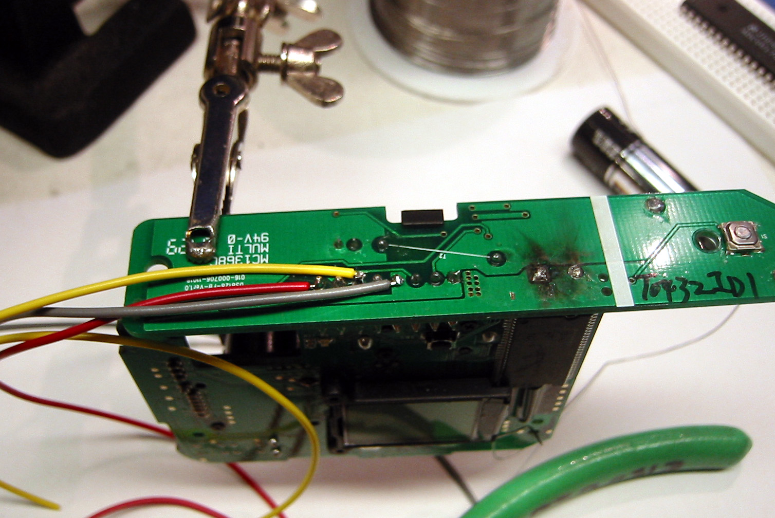
- Discharge the flash capacitor:
Carefully hold the main PCB board as shown, preferrably using a 'helping hands' tool or vise. make sure the jaws don't short any exposed components.

Note the large capacitor, when the flash is charged, this capacitor has 450V across the leads. Before any hacking can be done this capacitor must be discharged safely. Holding the large flathead screwdriver by the plastic handle, touch both capacitor leads, there will be a large pop and flash as 3300uF discharges across the screwdriver tip. Electrolytic capacitors can hold their charge for a surprisingly long time, and they also exhibit "dielectric soak" where they appear to 'recharge' themselves (see Sprague's explanation.) For these reasons, you must always discharge the flash capacitor before you start working with the board, even if its been unused for a long time, and every few minutes while the circuit is being worked on.
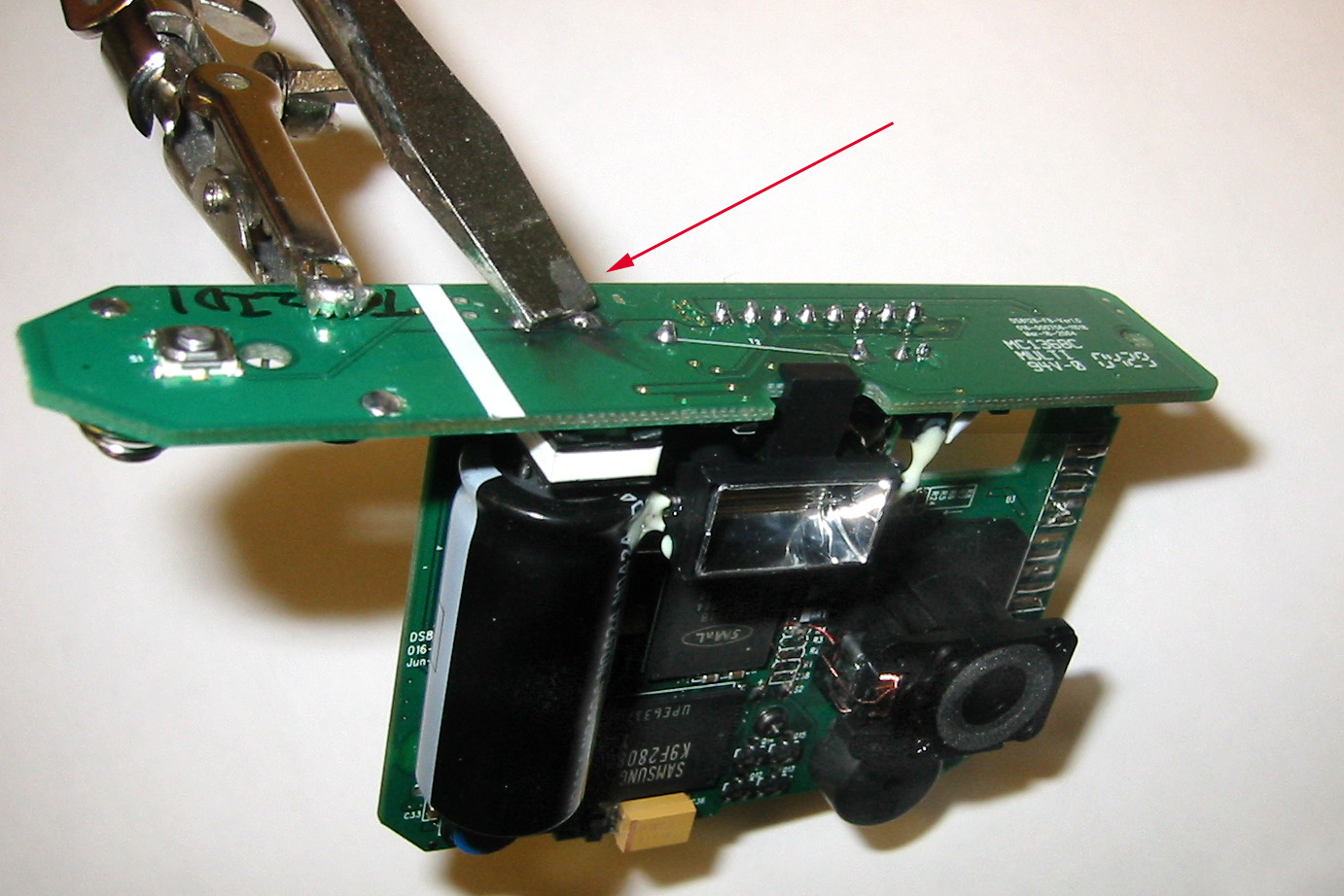
- Attach the control and power wires:
Cut 3 wires (preferably 22ga or thinner, stranded core) in three different colors, two of which are red and black. The red wire will carry +3V, the black wire is the common ground, and the third wire is the shutter signal wire. Strip the ends, and tin them. Solder the wires to the pins where the main board connects to the flash board. Staring from the shutter button, the black wire connects to pin #4, the shutter wire to pin number #6, the red wire to the last pin, #8.

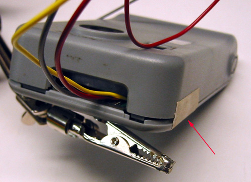
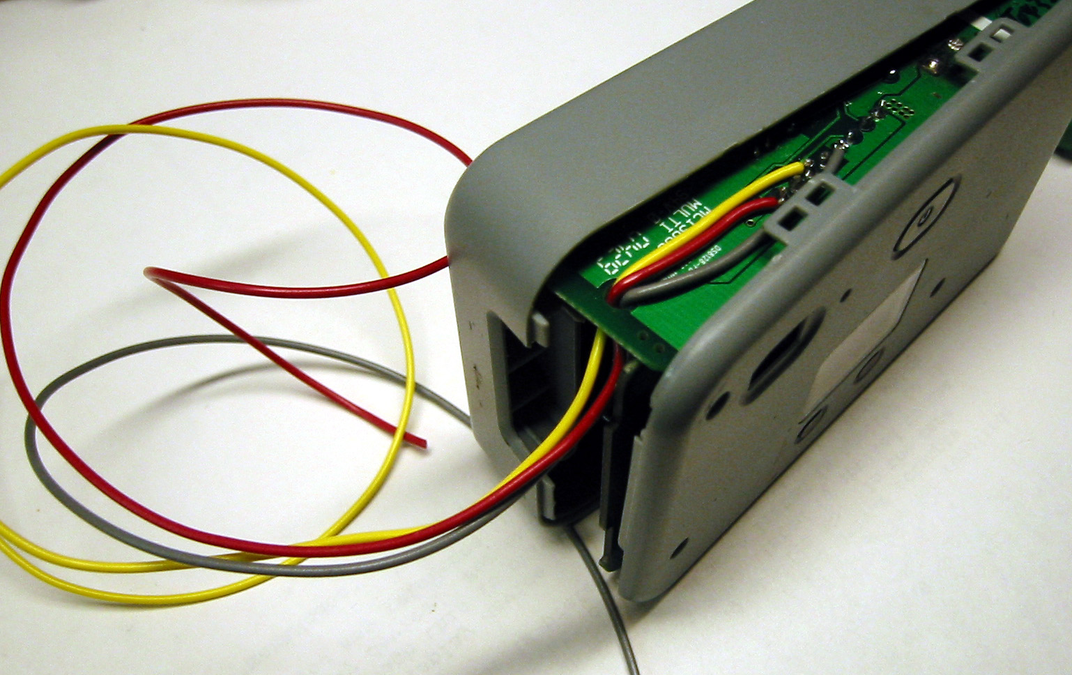
Thread the wires through the small hole in the flash board. Put the plastic case back on, so that the wires come out the side of the case.

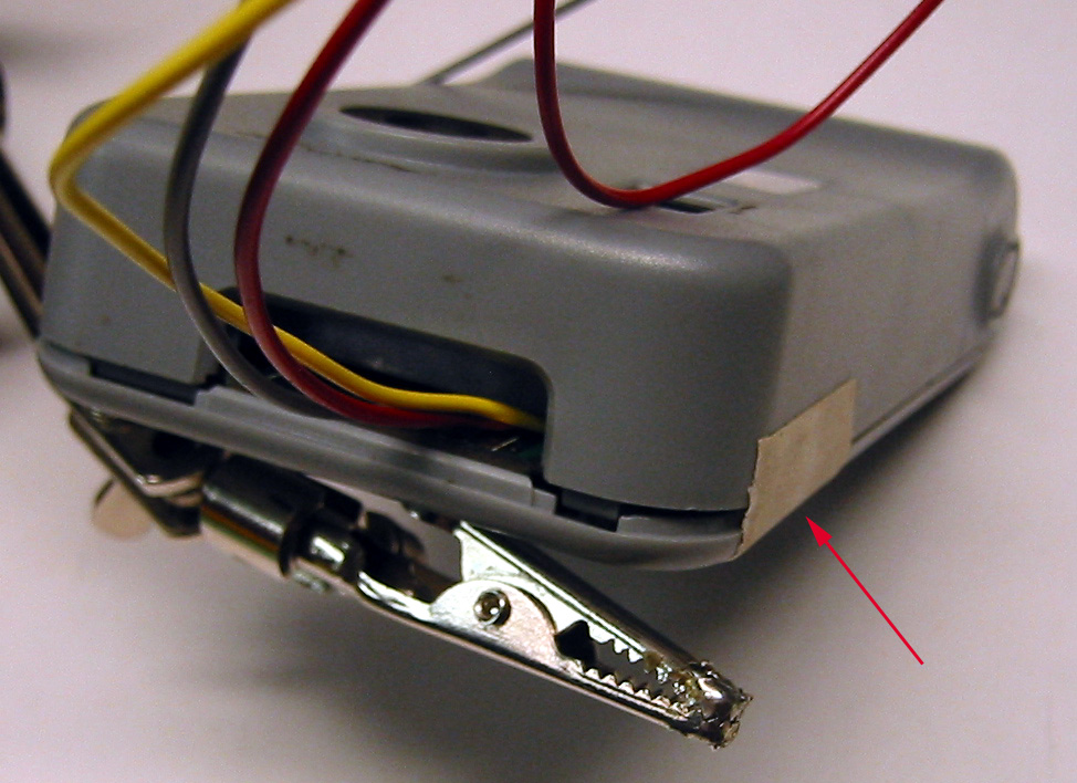
- Reassemble the camera:
The case won't close all the way, so don't try to or you might break the case or cut through the wire insulation! Insert the two screws near the bottom of the case, and use a piece of tape to secure the top.
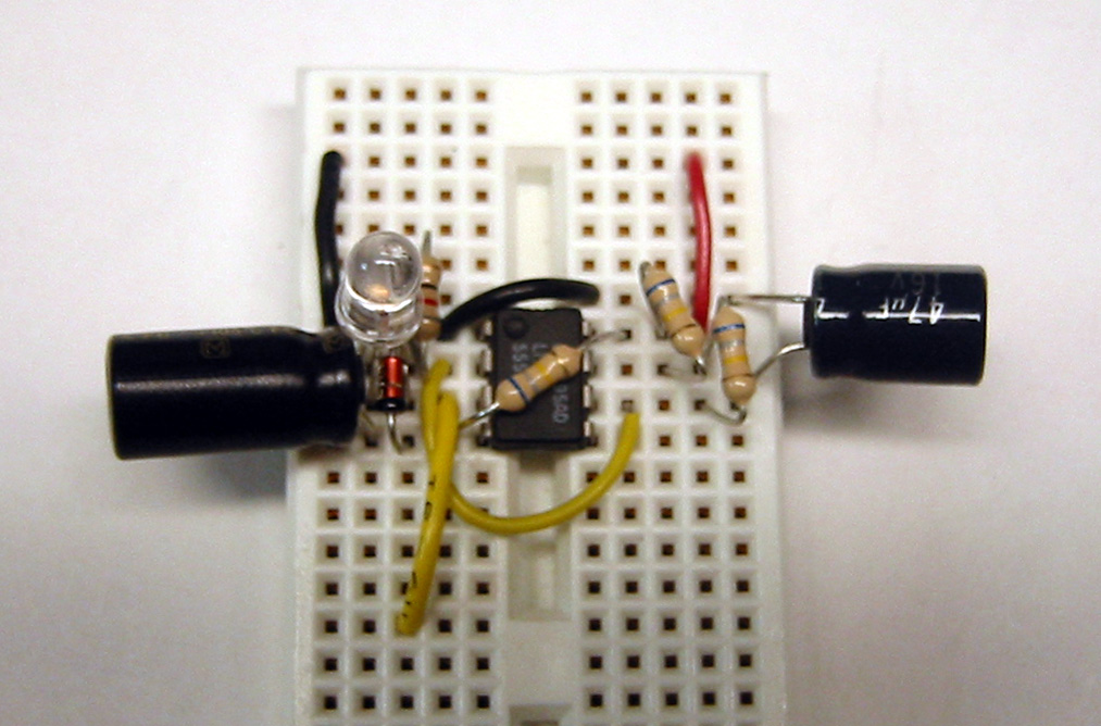
- Build the controller circuit:
You might want to start out by building it on a solderless breadboard, and seeing if it works properly, before soldering it on a perf-board.
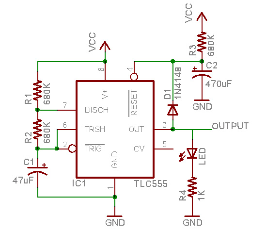
Be sure to use a CMOS 555 timer chip, such as the TLC555 or the LMC555. Other chips, such as the NE555, LM555, etc. will not work at 3V power! Also note that the LED, diode, and capacitors are polarized, and wont work if they're plugged in backwards. Electrolytic capacitors have a marking on one side (usually a negative sign next to the negative lead). Diodes have a painted stripe on the negative side, which is the end that the 'arrow' in the symbol points to. LEDs differ, sometimes they have a flattened side, or if you can see inside, there are two parts, one that looks like a 'cup', this is the 'negative' side, or the side the arrow points towards. Another good way to test is to connect the LED, briefly, to the red and black wires coming out of the camera, it will light up when the negative side is connected to the black wire.

VCC in the schematic will connect to the red wire coming out of the camera, GND is the black wire and the output goes to the shutter trigger wire.
- Test the circuit:
Connect the red and black wire from the camera to VCC and GND of the circuit. After 2 or so minutes, the red LED should light up, after about a minute more, the red LED should go out. The LED will then flash on and off, about once a minute for a full cycle. (The first time the LED lights up will be longer than the other times, so dont count that when timing the LED.) If the circuit is working, first check that there is 3V between the red and black wire. Then use a multimeter to check the voltage across the 470uF capacitor, it should slowly rise from 0V to 1V or so, then jump up to 3V. If it isnt slowly rising, make sure the diode isn't backwards. Once that is working, check the voltage across the 47uF capacitor. Once the reset pin is above 1V, the capacitor should slowly charge up to about 2V and then discharge to 1V, then up to 2V, etc. If that's working correctly, check if the LED is in backwards, or if it's not red, amber, or yellow. Try removing it and checking the output pin voltage. It should flip between about 2V and 0V, one cycle per minute.
- Adjust the circuit (if desired):
By swapping in larger resistors, you can extend the delay times. To make the startup delay longer, swap out R3. To make the between-pictures delay longer, swap out R1 and/or R2. Make sure that from when the circuit is turned on, the LED lights up and goes out within 3 minutes, so that the camera doesn't automatically turn off before you want to start taking pictures.
- Rebuild the circuit on solder prototyping board (perfboard) so its more durable (optional):
Since you can't disconnect the power wires, be sure to solder in a switch so you can turn it on and off. Test it again to make sure the LED blinks at the desired rate.
- Test out the full system:
While the board is off, discharge the two capacitors with the screwdriver to make sure they start at 0V. Connect the trigger wire to the output line of the 555. Turn on the circuit, then turn on the camera. When the LED turns off for the first time, the camera should take a picture. (If it doesnt take a picture, try connecting the trigger wire to the black wire. If it still doesn't take a picture, then you probably didnt solder the trigger wire to the right pin.)
- Take flight!
Mount the camera and control board to your kite.
- Disconnect the control circuit and develop images:
Once you've taken all the pictures you want, land the kite, and check the "Pictures remaining" counter to verify the circuit worked. After all the pictures are taken, disconnect the circuit by opening the camera, discharging the flash capacitor, and desoldering the wires. Reassemble the camera and have it developed where it was purchased.