|
Make Something Else Home |
OverviewTheoryMakeResources |
| Hardware Modification | history last edited: September 27, 2004 |
| The Famous 555 |
|
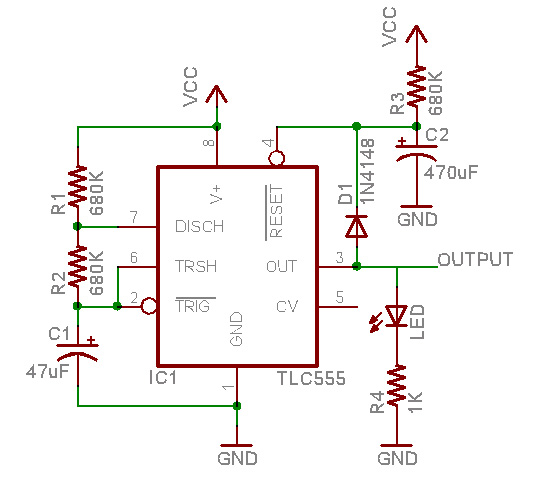
The LM555 timer chip is famous for being so versatile at a low cost. With only 2 resistors and a capacitor, the 555 can generate a square wave of almost any frequency (up to 2MHz) and duty cycle.We'll be using the 555 to generate the 60 second-period square wave that triggers the camera.
Unfortunatly, the LM555 requres 4.5V at least to run, and we only have 3V power. This means we have to use one of the CMOS-versions, such as the TLC555 or the LMC555. Using one of the non-CMOS versions (SE555, LM555, SA555, NE555, etc) will not work! (Or may work intermittantly.) |
||
| Startup Timer |
|
Since it's going to take a few minutes to launch the kite and get it into position, it would be nice to have a startup delay. The camera itself will auto-shutoff after 3.5 minutes to conserve power, so our startup delay is only 3 minutes. The startup timer is implemented with a simple RC network connected up to the #RESET pin of the timer. The voltage on a capacitor being charged through a resistor is defined as: v(t) = V(1-e^(-t/RC)). The 555 has a pin, #RESET, which determines whether the 555 is active. When #RESET is low, the 555 is in reset mode (inactive), when it is high, the 555 is in timer mode (active). By tying #RESET to a large capacitor that is being charged by a large resistor, the #RESET line will slowly rise to 3V. Actually, depending on the chip, #RESET might be considered 'high' as low as 0.5V, although, according to the datasheet, the average voltage considered 'high' is 1.1V. Assuming the average value, and given that we want a 3 minute delay, we can solve the equation with v(t) = 1.1 and t = 180. (V is given as 3V): 1.1 = v(t) = 3 (1 - e^(-180/RC)) Now solve for RC: RC = -180 / ln(1-1.1/3) = 394 Since capacitors don't come in that many values, we're
more constrained by the capacitor. Lets say we have a 100uF capacitor,
that means R = 4 megaohm resistor (approximately). |
||
| 1/60 Hz Oscillator |
|
After the startup, we want the 555 to oscillate at 1/60Hz. Since a picture is taken when the microcontroller in the camera detects a 'high to low' transition on the shutter pin, the duty cycle doesn't matter. The timing in a 555 works similarly to the RC network above, in our configuration, the 555 discharges a capacitor through one resistor and charges it through two resistors in series. While the capacitor is charging, the voltage on the output pin is high (3V), while its discharging the voltage is low (about 0V). The capacitor charges until it's voltage is 2/3V and discharges until its voltage is 1/3V where V is the supply voltage (so the timing is independant of what voltage the batteries are at) The width of the 'high' portion of the square wave is therefore: Rc*C*(- ln( 1 - (2/3 V)/V ) + ln( 1 - (1/3 V)/V )) = Rc*C * ln( (1-1/3)/(1-2/3) ) = Rc*C* ln(2) = .7*Rc*C Where Rc = charging resistance, C = capacitor. Likewise, the width of the 'low' portion of the square wave is .7*Rd*C where Rd = is the discharge resistance. So to get a total width of 60 seconds: 60 = .7 (Rc+Rd)C = .7 (2R1+R2)C Assuming R1 = R2 = R, then if we choose a 47uF capacitor, R = 570K. Of course, choose any values that make the above equation true. (As a note, the first time the capacitor charges, it starts at 0V not 1/3V so it'll take 50% longer, so the time from turning on the circuit to the first high to low transition is actually the startup time + positive width * 1.5) |
||
| Everything Else |
|
To test your setup, use an LED and 1K resistor. When the LED transitions from on to off, the camera will take a picture. Before hooking up the shutter wire to the circuit (or while the circuit is on a breadboard), use the LED to measure the timing. Any noise on the power supply can cause the #RESET line to bounce (and theres a lot of noise, particularly when the flash fires). Then can end up flickering the output line, causing a picture to be taken inadvertantly. A simple diode from the output to reset line helps keep the reset line high once the circuit is out of startup-delay mode. |
||