 |
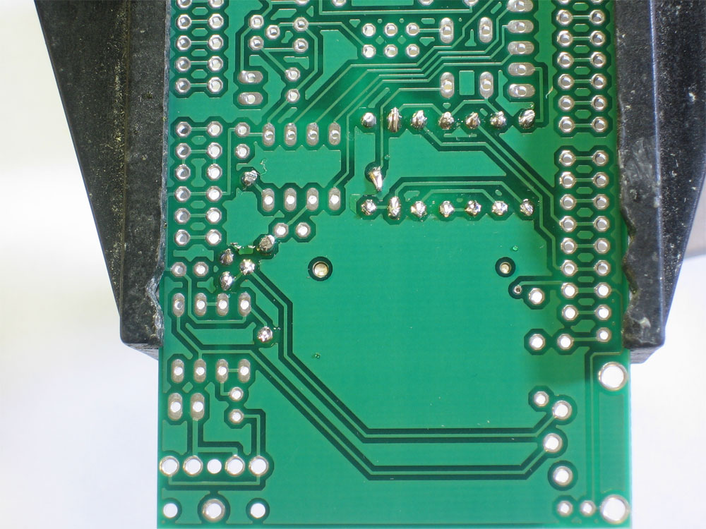
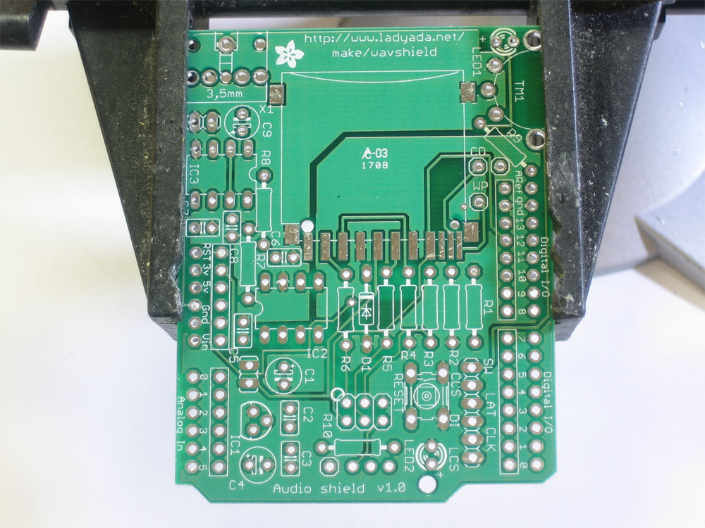
Get ready by placing the PCB in a vise |
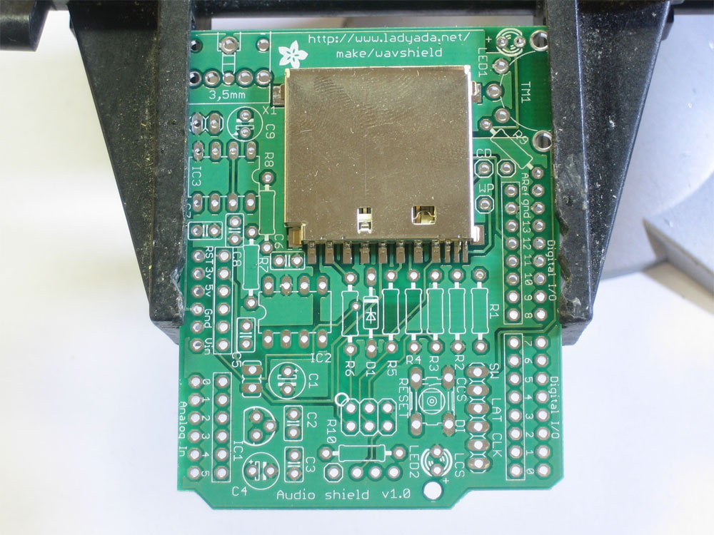 |
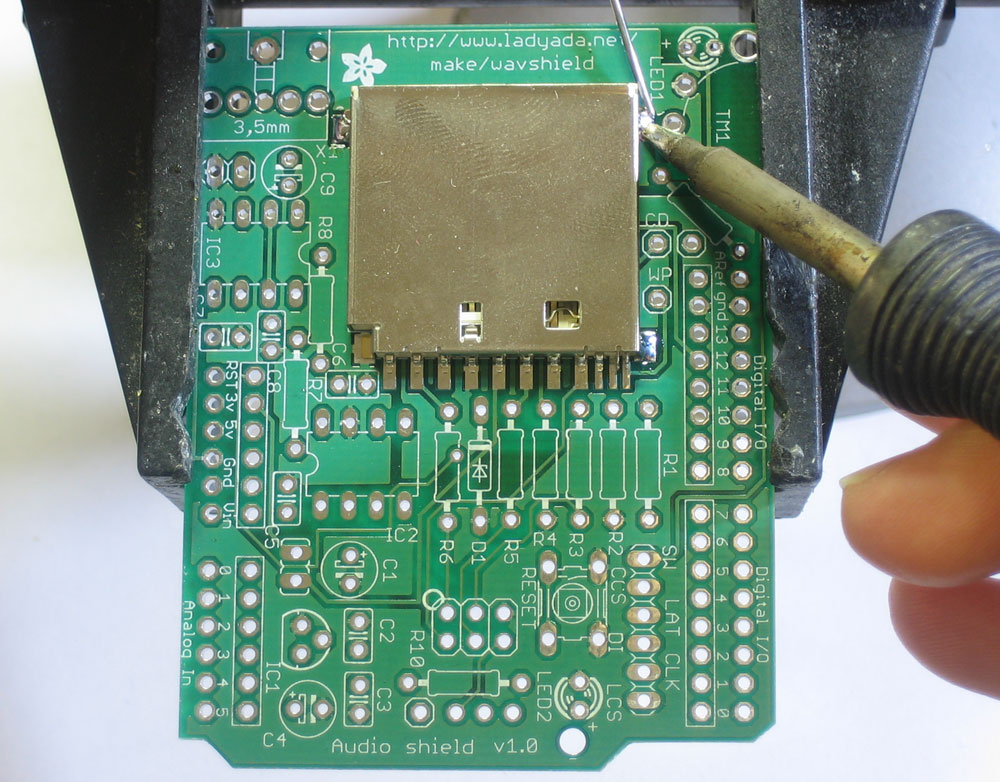
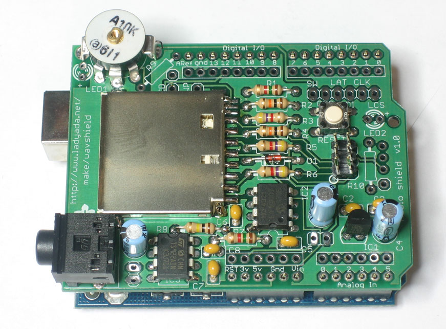
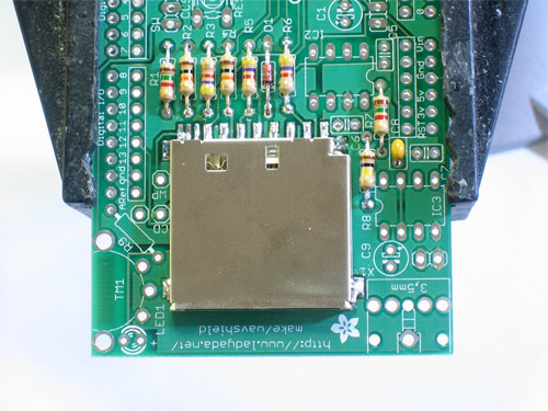
We're going to the SD card first. While surface mount parts are a little tougher than thru-hole, this piece has pin spacing of 0.1" so it is quite easy. Doing it first also gives us lots of working room. The holder should 'snap' perfectly into place thanks to two bumps on the bottom. |
|
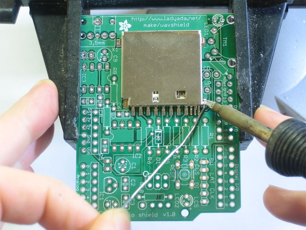
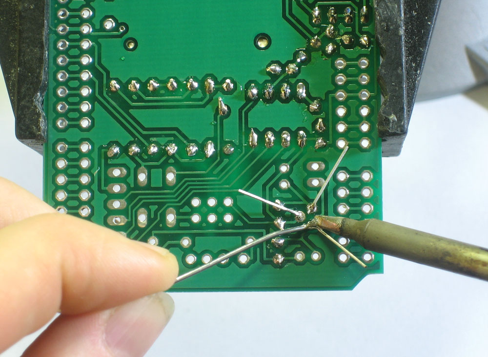
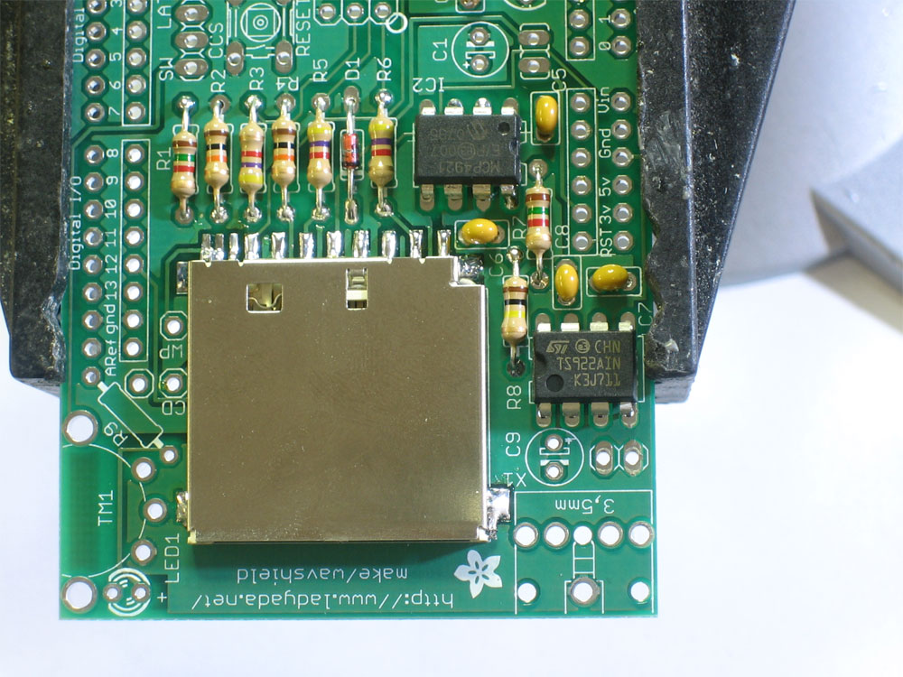
We'll start with the four side tabs that are used to mechanically secure the card holder in place. Heat up the metal tab and the pad (the silver square beneath it) for 3 seconds with a hot soldering iron, then poke just a bit of solder in. Do this for all three corners. Once this is done you should not be able to lift the card holder |
|
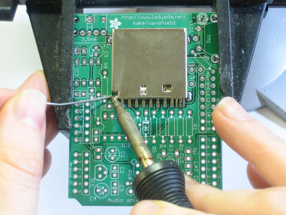
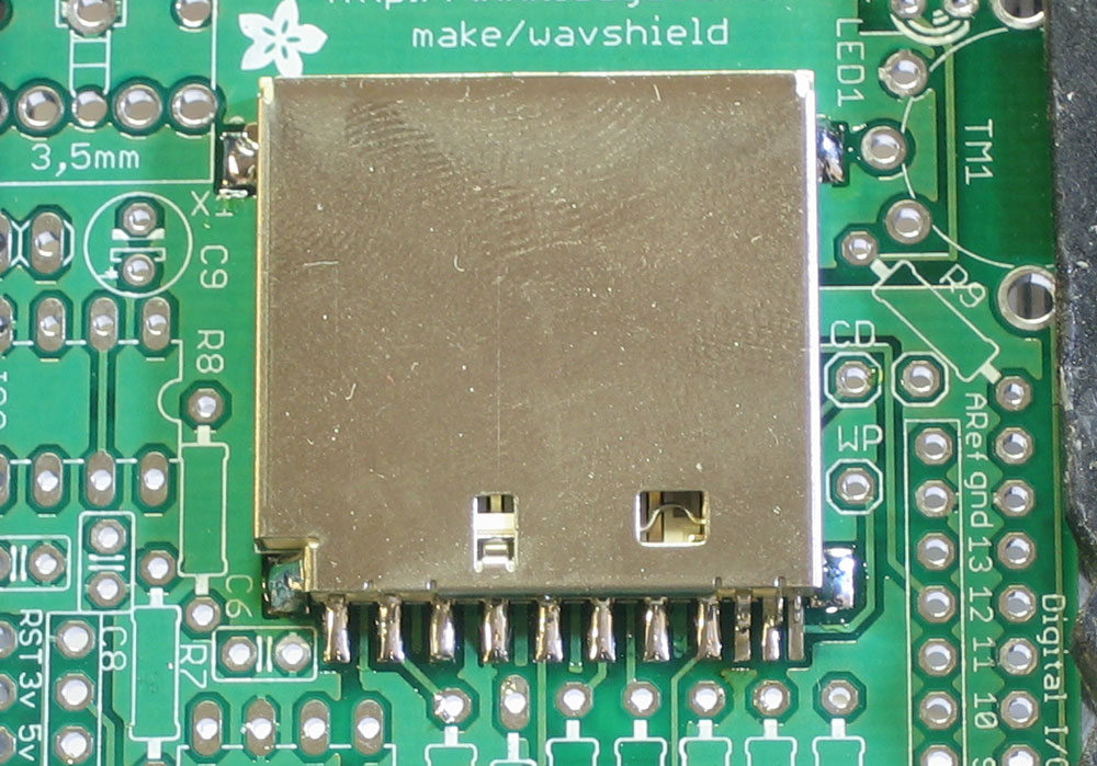
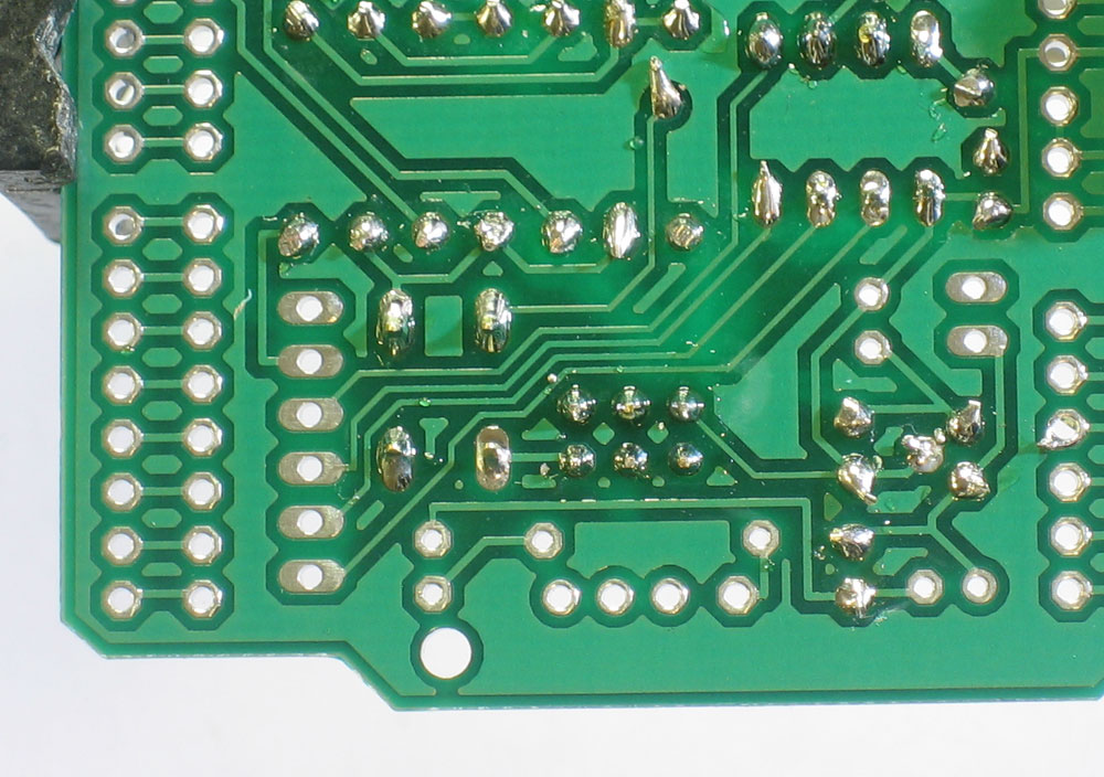
Now go thru and solder the 8 leftmost pins that stick out from the holder. The three rightmost pins are thinner and closer together so they are tougher to solder. Luckily they are not used and you simply skip them (although the photo shows them done) Check that you have no solder bridges - the pins should not be soldered to the metal body of the holder or to each other |
|
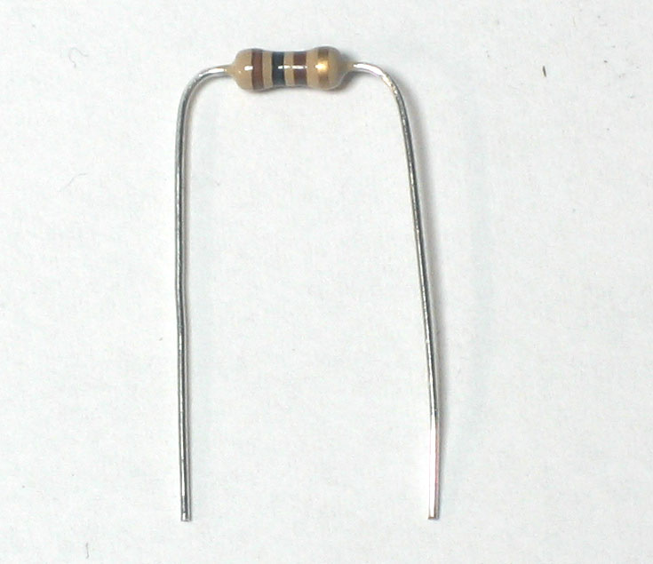
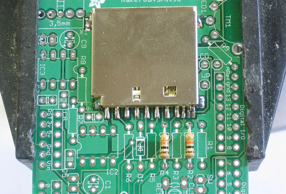
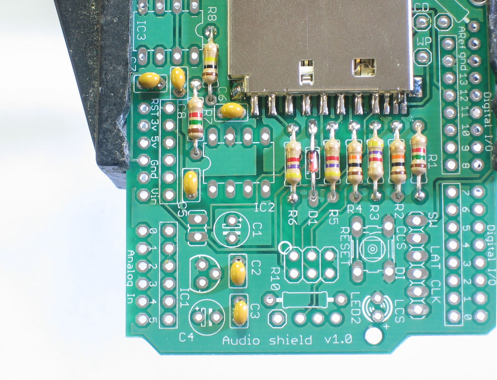
Next, we will solder all of the many resistors. The 10K resistors R2 and R4 are first. Form them into staples (as shown left with a 100 ohm resistor), then place them so they sit flat against the PCB, in the correct locations. Resistors don't have polarity so they can go in 'either way' and work fine! Once placed, bend the leads out so the resistors dont fall out If you're using an NG Ardiuno, replace R2 with a 1.0K-2.0K resistor |
|
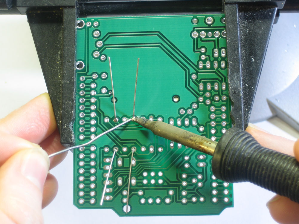
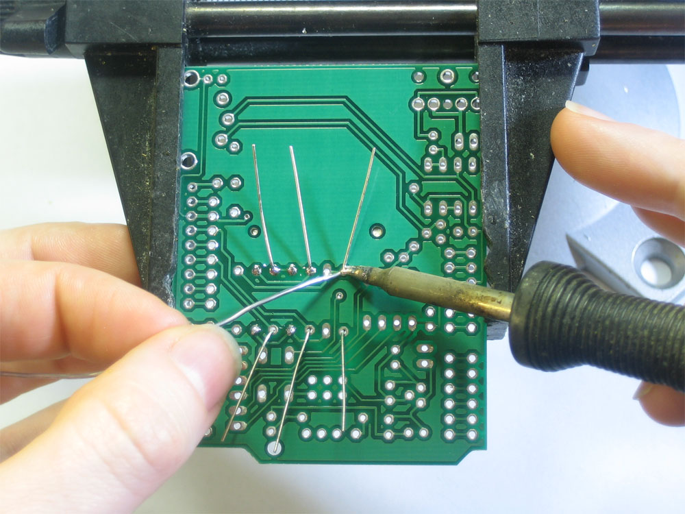
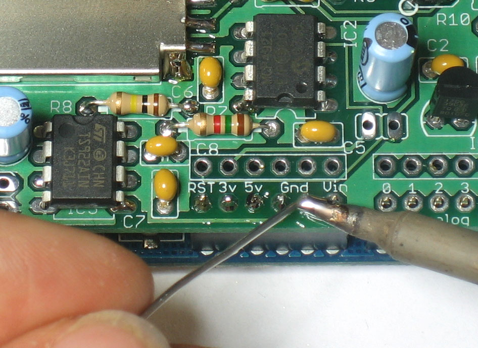
Solder the leads to the pads (metal ring) by heating both with the side-tip of the iron for 3 seconds and then poking in a bit of solder |
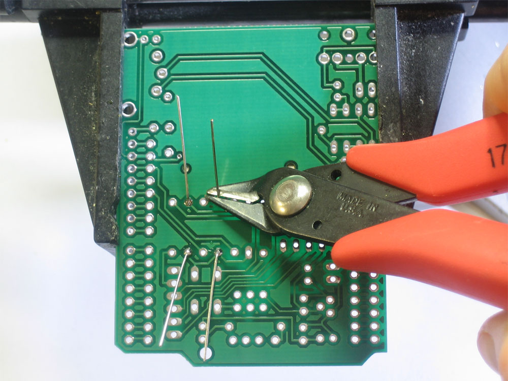 |
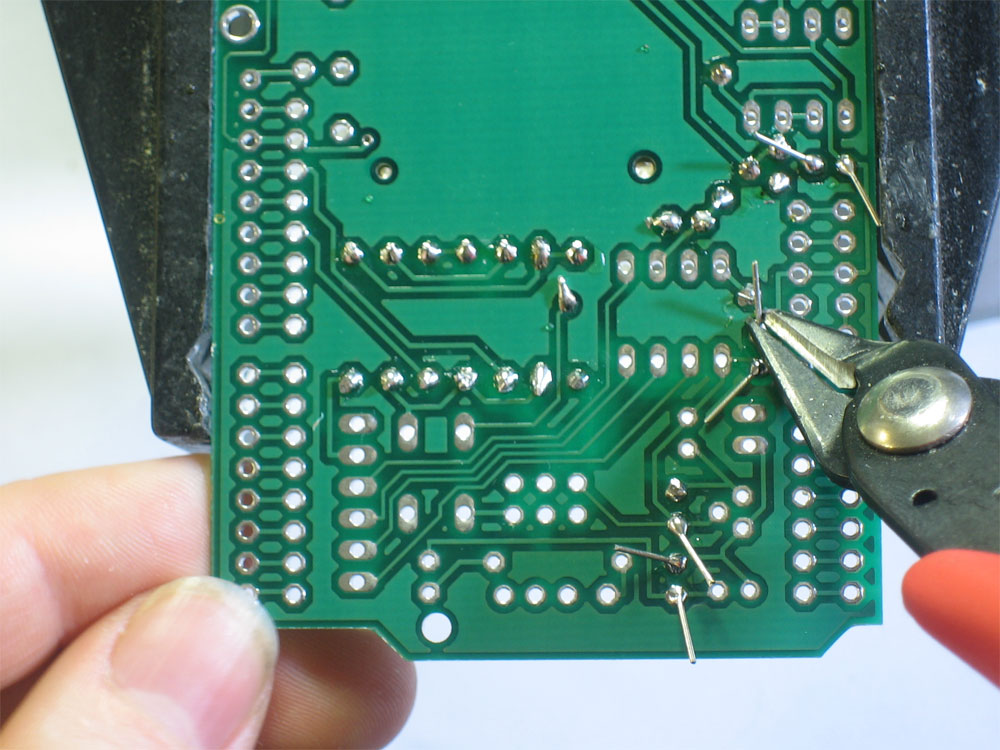
Use your diagonal cutters to clip the leads off just above the solder joint |
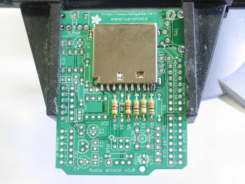 |
Next place the three 4.7K resistor R3 R5 and R6 Make sure they go in the right locations! If you're using the shield on an NG arduino, use a piece of wire instead of R5 |
|
Solder and clip the leads of the three resistors |
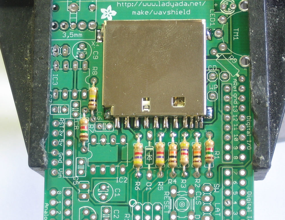 |
Finish up the resistors by placingR8 (100Kohm), R1 (1.0K) and R7 (1.5K) In the photo, R1 is shown as 1.5K...this is a mistake! (It was too flakey for me and I reduced the resistance). Make sure you place a 1.0K resistor in R1! Solder the components |
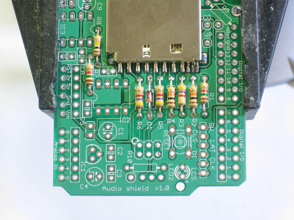 |
Next comes the 3.6V zener diode. A diode is sort of resistor-shaped except that it has a black stripe on one end. Diodes are polarized and must be placed the correct way to work so make sure that the black stripe on the diode matches the white stripe on the silkscreen position indicator |
|
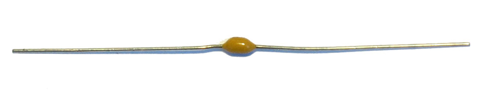
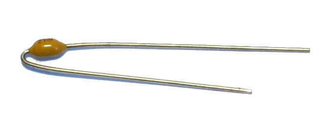
Next is the 0.01uF ceramic capacitor C8. The tricky part here is that in older kits there are many 0.1uF ceramic capacitors in the kit that look identical to the 0.01uF! The way to tell the difference is look for the 103 printed on it. If it says 104 then it's a 0.1uF. Make sure it says 103! This capacitor forms the output low-pass filter for the audio so its important to have the right value. Lately I have been shipping kits with axial (long-ways) package, not radial (side-ways) package. These are longer (see left) and are easy to bend over for soldering. This way there is less confusion. Either way, try to spot the 103 marking |
 |
Place the capacitor right next to R7. Ceramic capacitors are non-polarized and can go in 'either way' |
|
Solder and clip the small capacitor leads |
 |
Once you're sure you have C8 correct, you can place the remaining 0.1uF ceramic capacitors C2, C3, C5, C6 and C7. Ceramic capacitors are non-polarized and can go in 'either way' |
|
Solder and clip the capacitors |
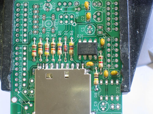 |
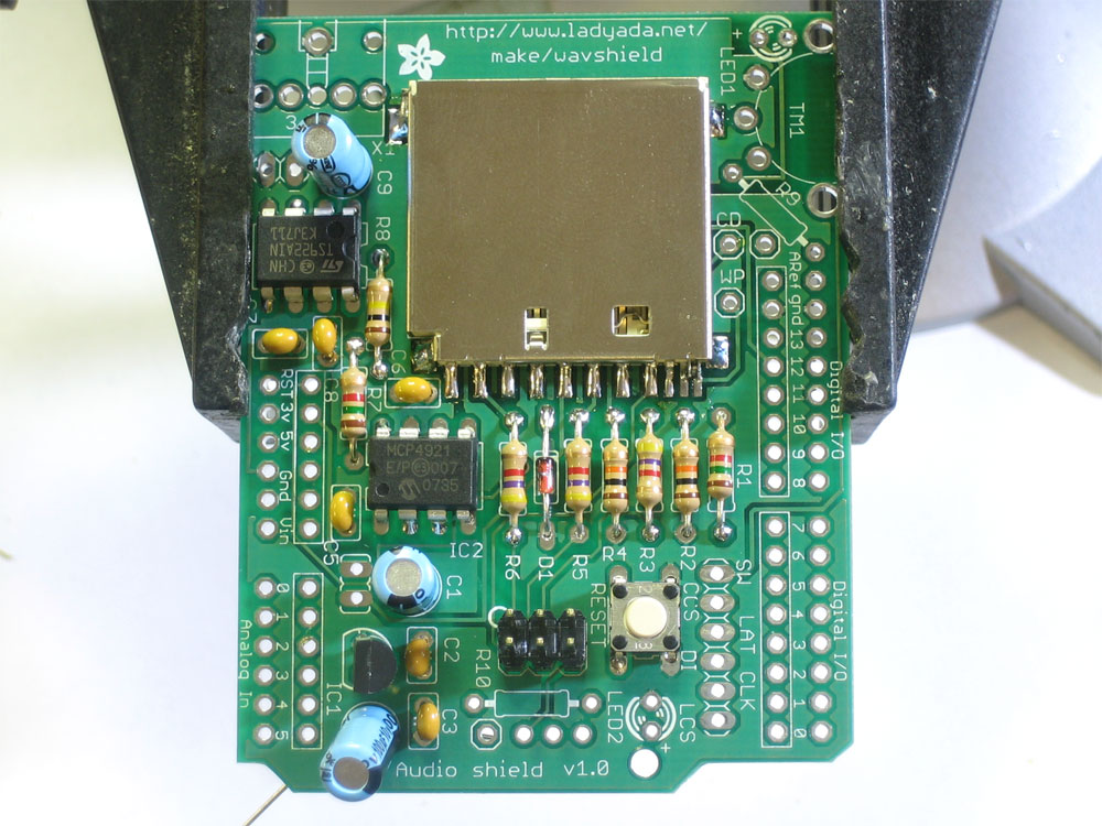
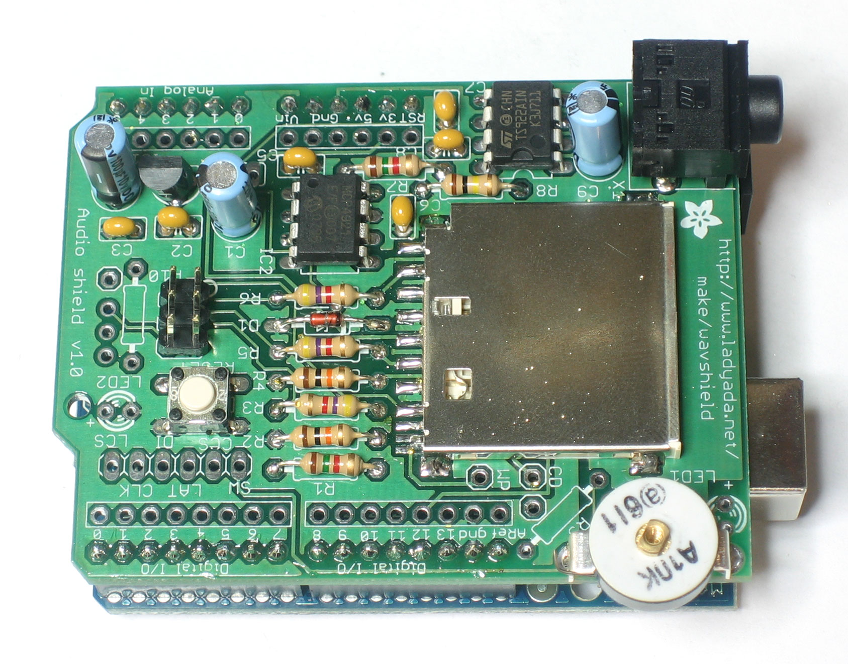
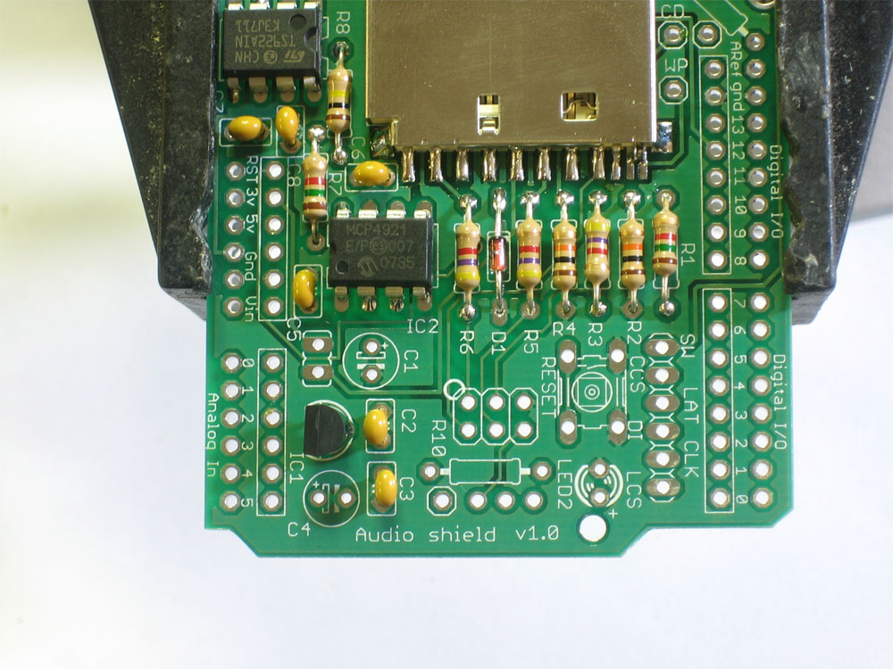
Next is the DAC (digital-analog converter) IC2. This is what turns the data into music. Make sure you pick the DAC to solder in here, it says MCP4921 on it and has a stylized M. The chip has a notch in one end and that notch must line up with the notch in the silkscreen. In this photo, thats on the right. |
 |
Flip over the board and solder in each pin of the chip. The pins are already quite short so you dont have to clip them |
 |
Next is the operational-amplifier (op-amp) IC3. It is used to buffer and amplify the output, so that it can drive a small speaker or headphones. This is a similar-looking chip to the DAC. Again, check that the notch matches the silkscreen notch. In this photo, thats to the left. Solder it in, just like you did with the DAC |
 |
Next is the 3.3V regulator IC1 that provides a nice powersupply to run the SD card. The regulator comes in a semi-circular package, so make sure it matches up with the silkscreened image. |
|
Turn the board over and solder/clip the three leads. |
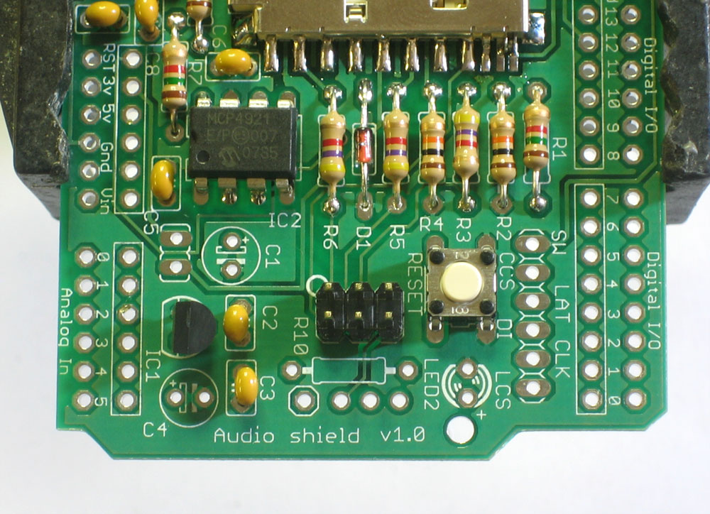 |
Next is the reset button and the ICSP header. These let you reset the Arduino manually, and reprogram it directly with a AVR programmer. The button will snap in, its symmetric so it goes in 'either way'. The header is also symmetric, make sure the long end sticks up |
|
Solder in both components. Their leads are pretty short so you dont need to clip them. |
|
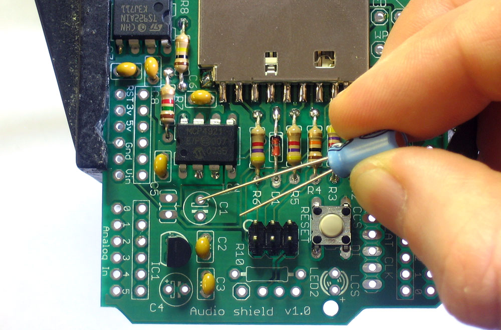
Next are the three electrolytic capacitors C1 C4 and C9 . Electrolytic capacitors are polarized so make sure they go in the right way! The long lead is the positive lead, make sure that goes into the hole marked with a + as shown here. |
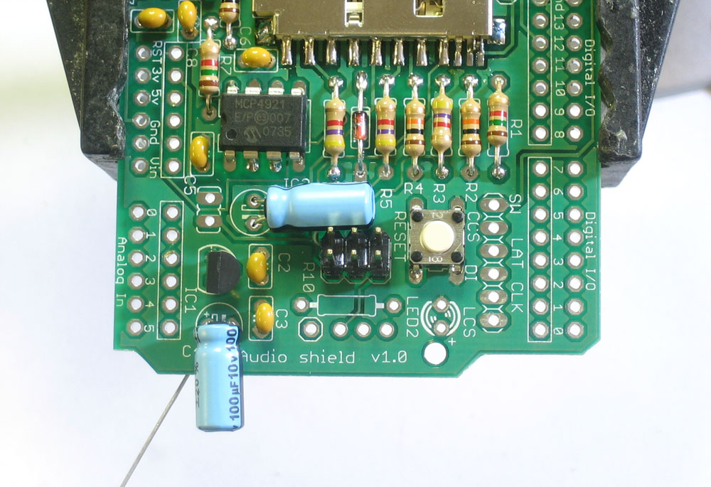 |
If you're planning to stack another shield on top of this one, you may want to bend the capacitors so they lay flat. |
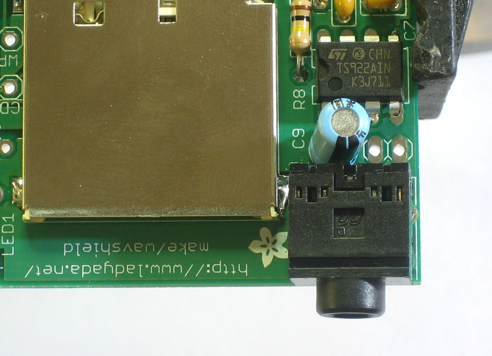 |
Next is the headphone jack. It snaps into place right at the edge of the PCB. |
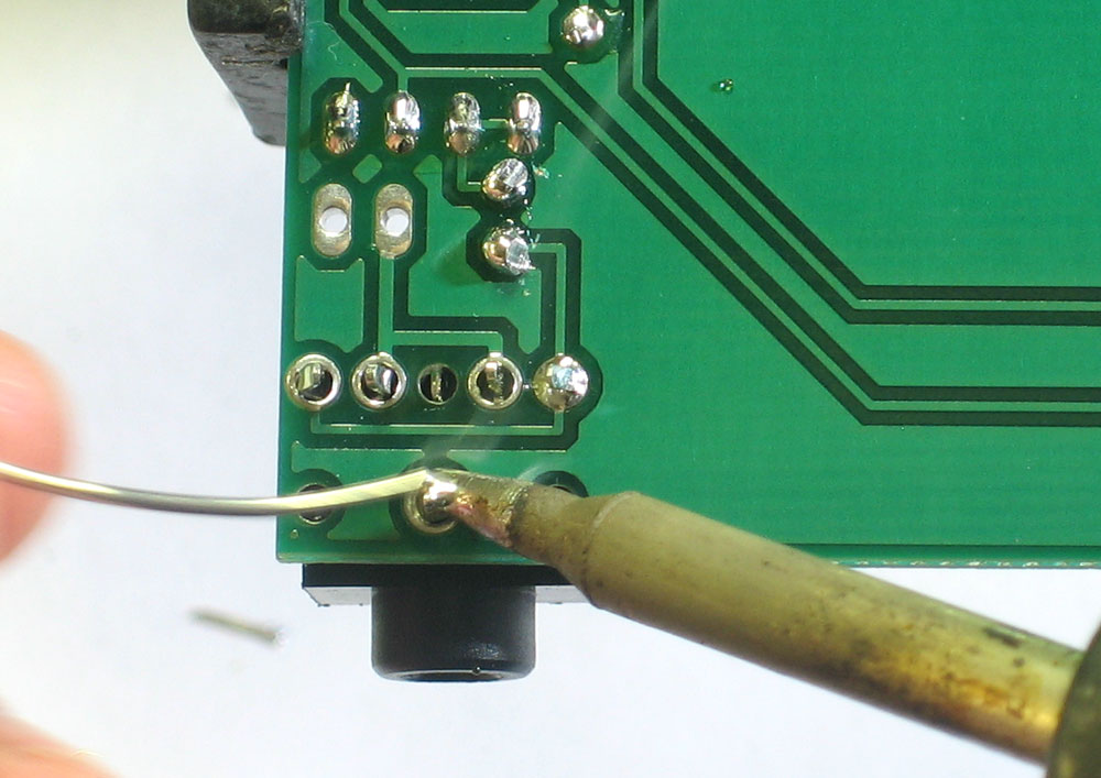 |
Solder the jack in place. You may want to clip the legs a little if you can, so that it will sit better on the Arduino. |
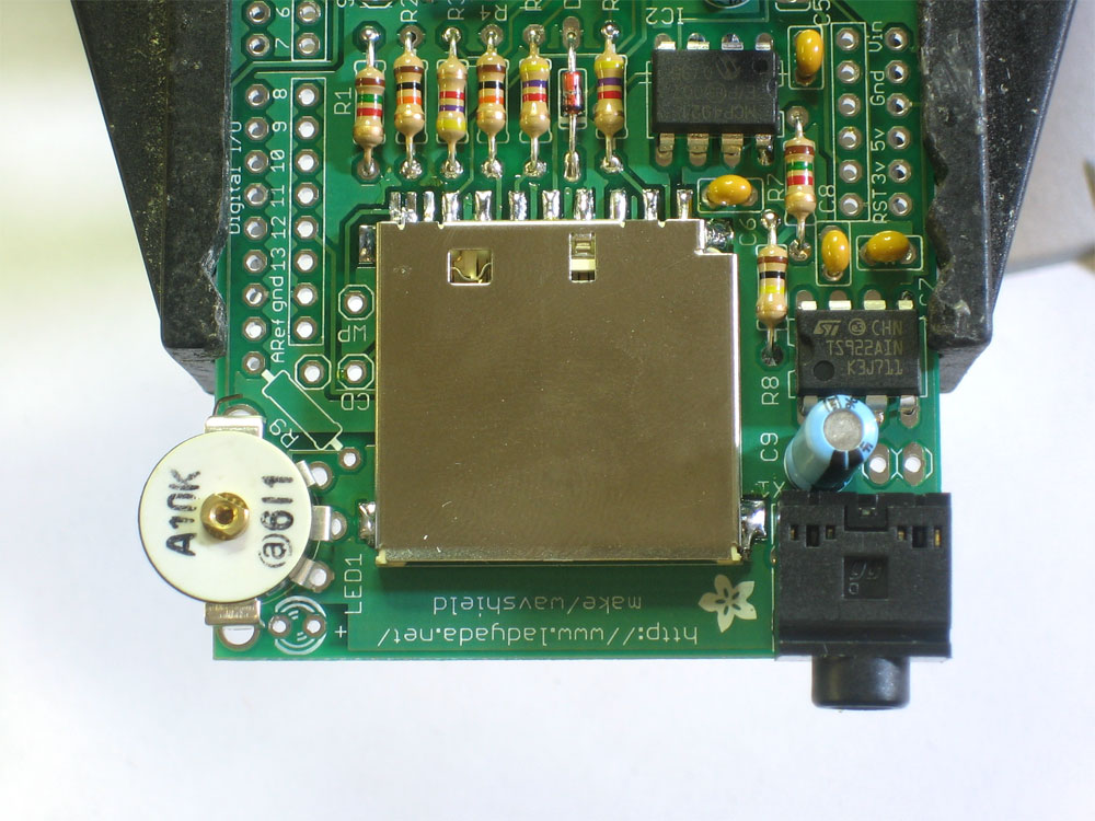 |
Next is the volume potentiometer TM1. This is an audio-type 10K pot. It will slip into place pretty easily. |
|
Solder all 5 pins of the potentiometer. Use plenty of solder so that it has a lot of mechanical strength |
|
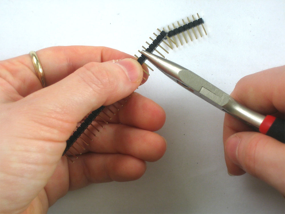
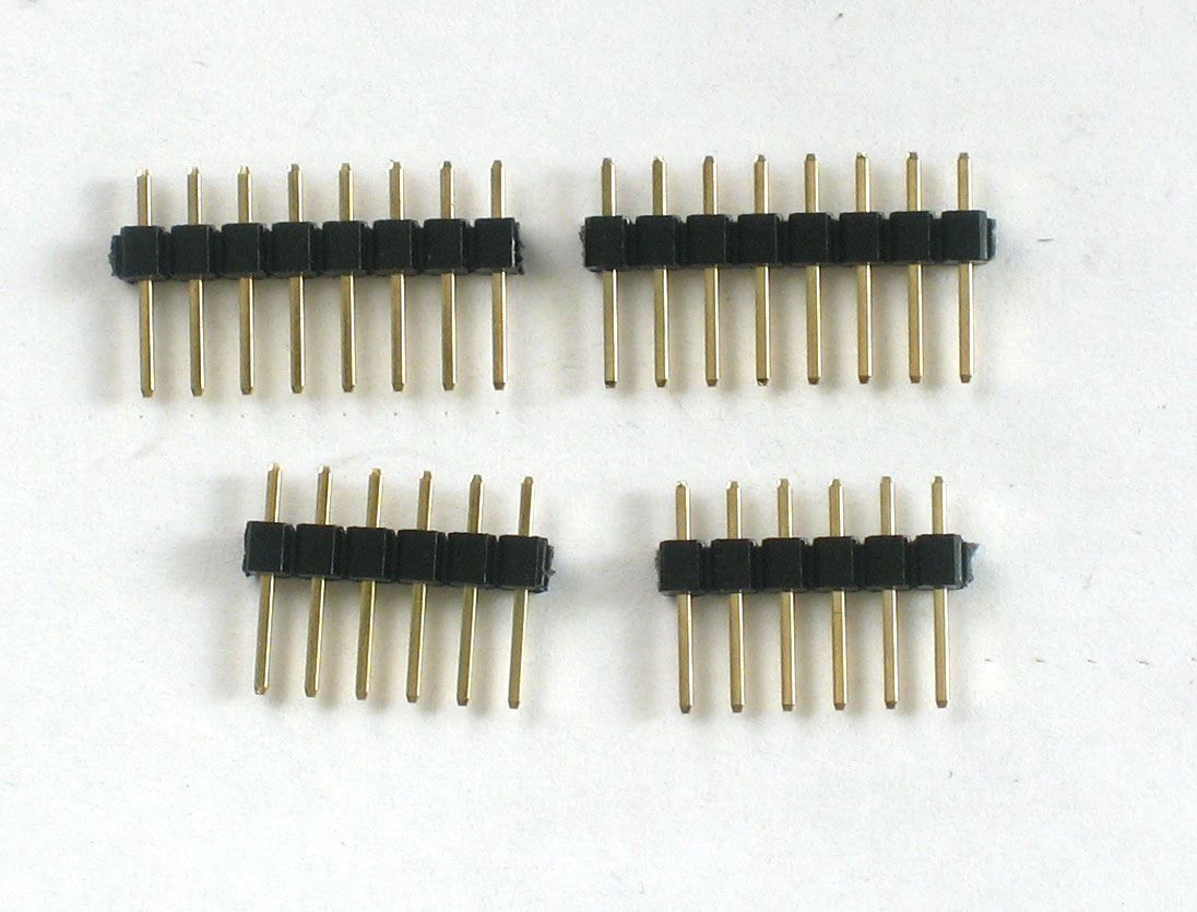
Next, break the 36-pin header strip into smaller sections so that the shield can be placed on the Arduino. You can use pliers or diagonal cutters. Clip off 2-6pin and 2-8pin pieces. |
|
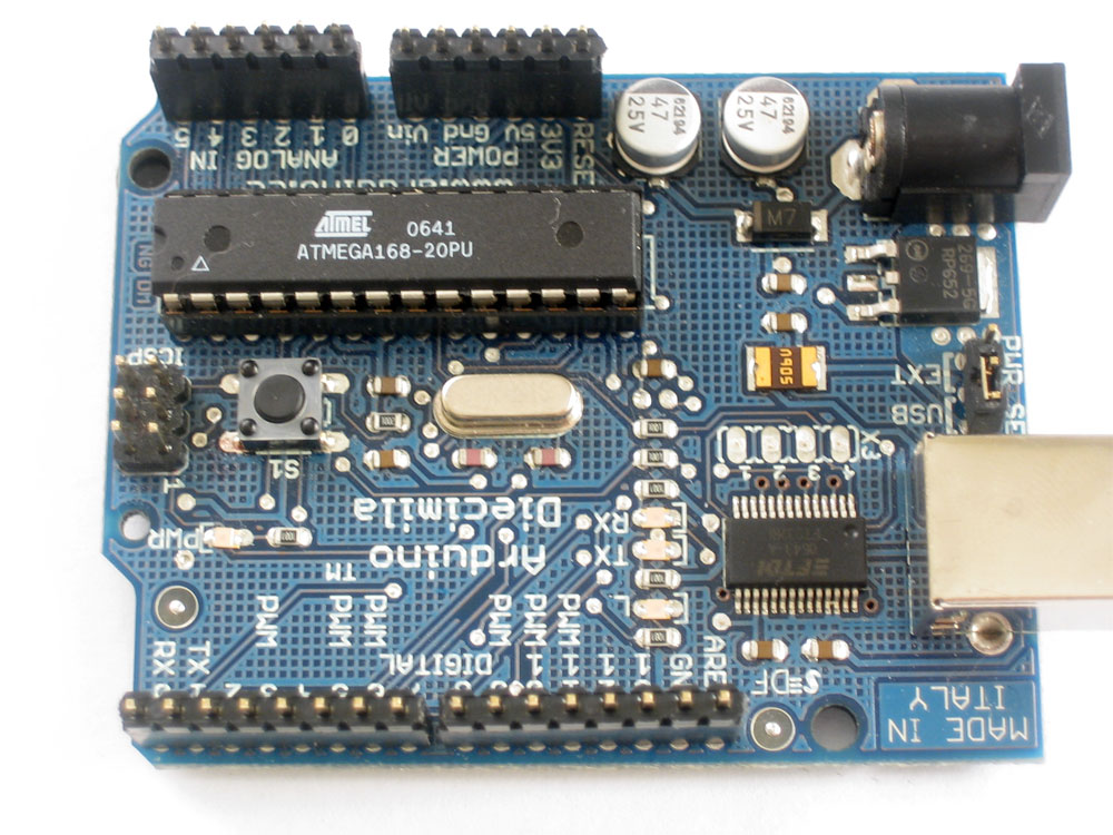
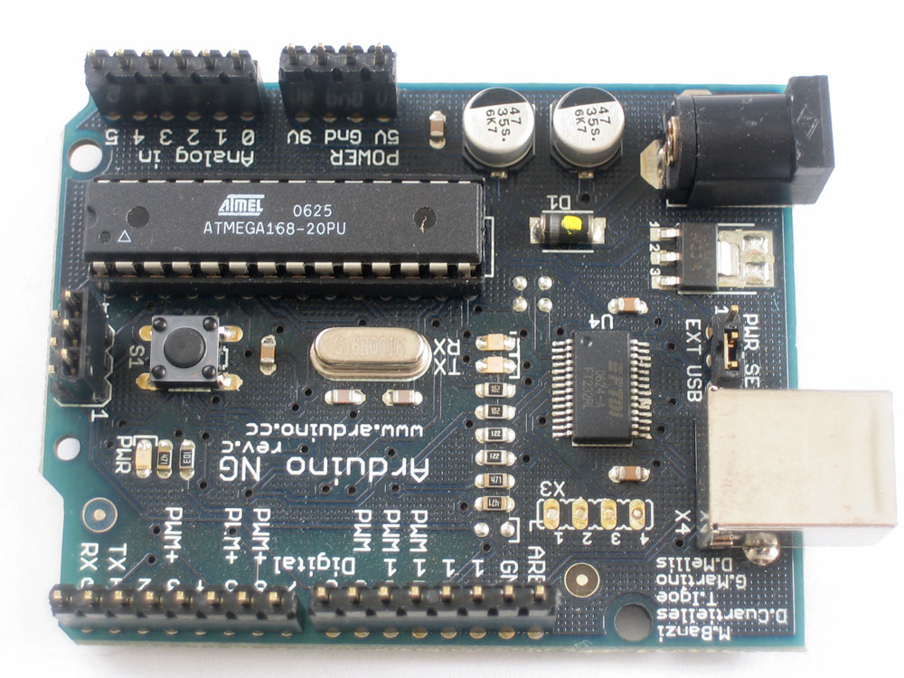
If you're using a Diecimila Arduino, place the 6 and 8 pin headers into the female sockes. If you have an NG Arduino, you can place a 3-pin female header (not included) as shown, which will let you use the reset button. |
|
Place the shield PCB onto the arduino so that all the holes match up with the header. |
|
Solder in each and every pin of header |
|
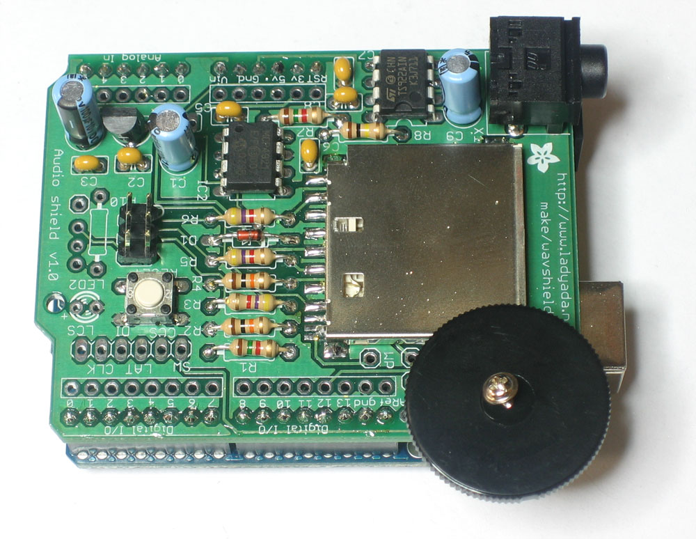
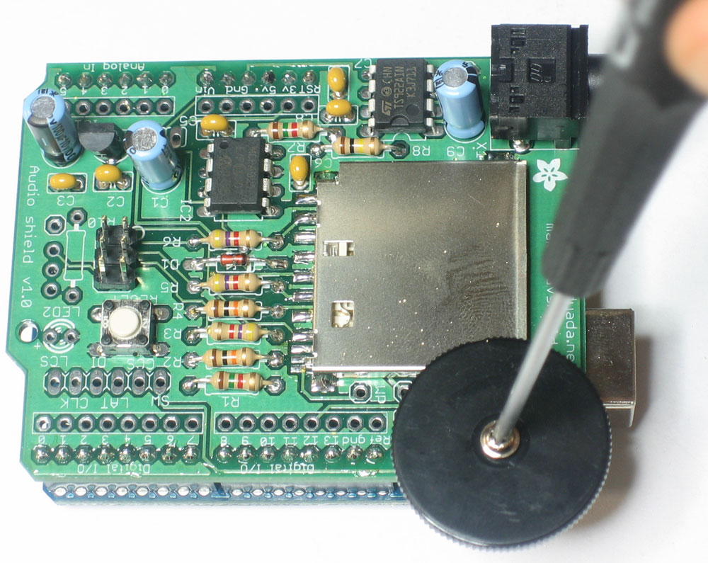
Next you can install the thumbwheel. Use a #0 screwdriver. Align the thumbwheel so it 'grabs' the potentiometer, then gently screw it in place. |
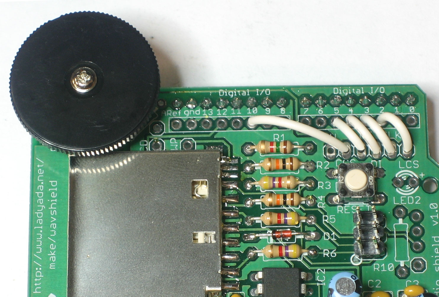 |
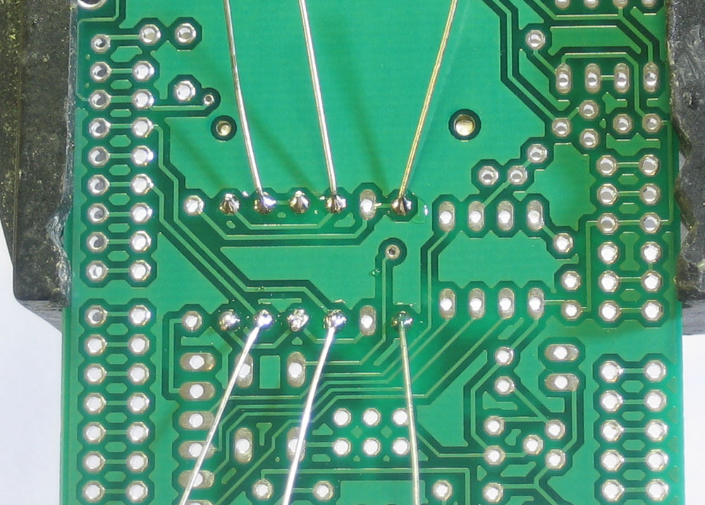
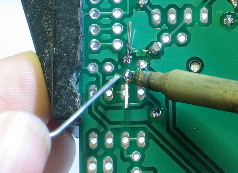
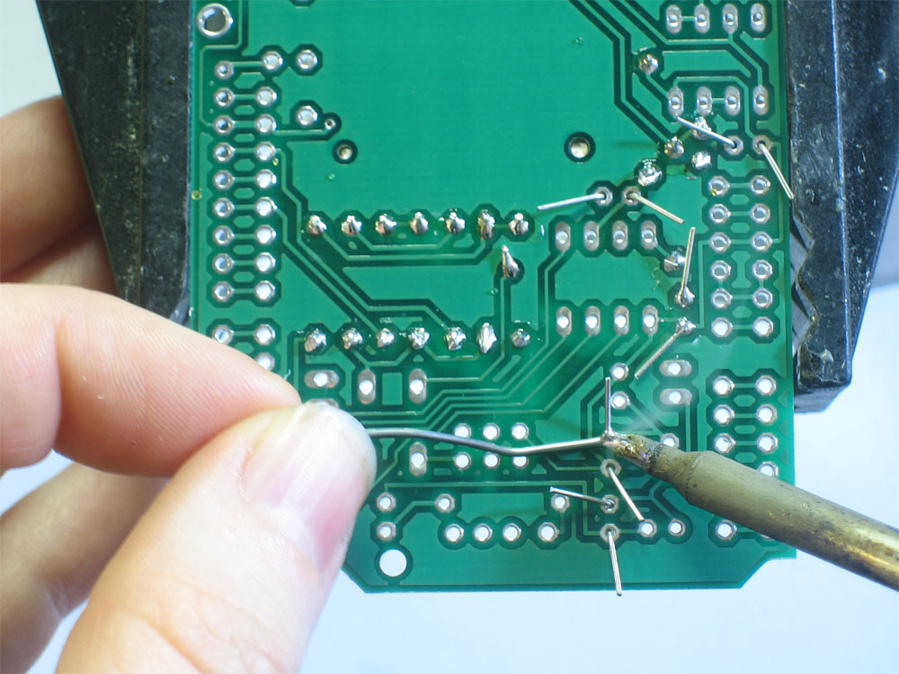
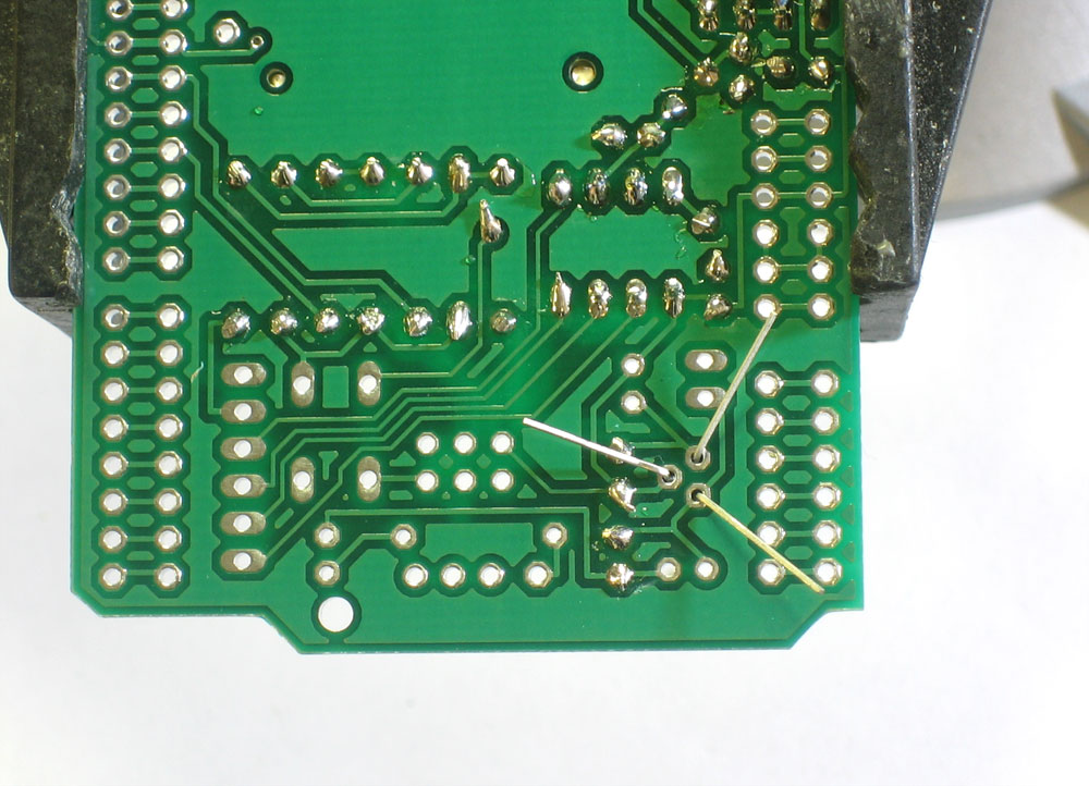
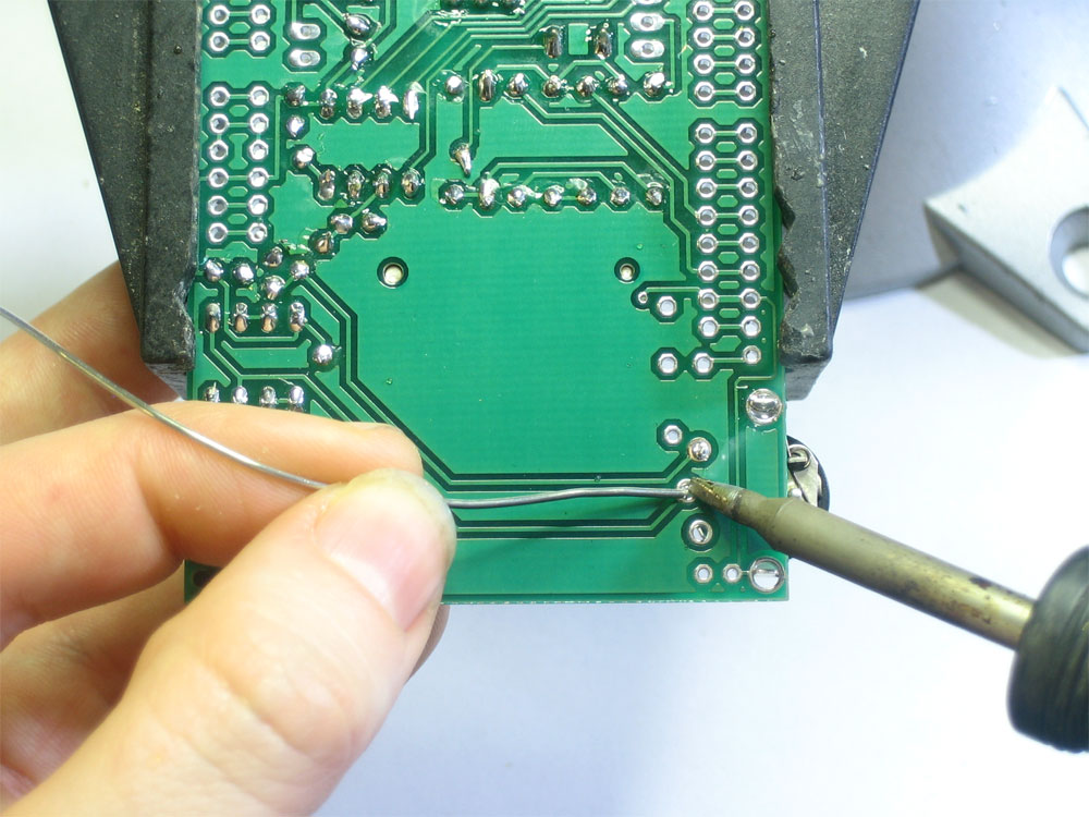
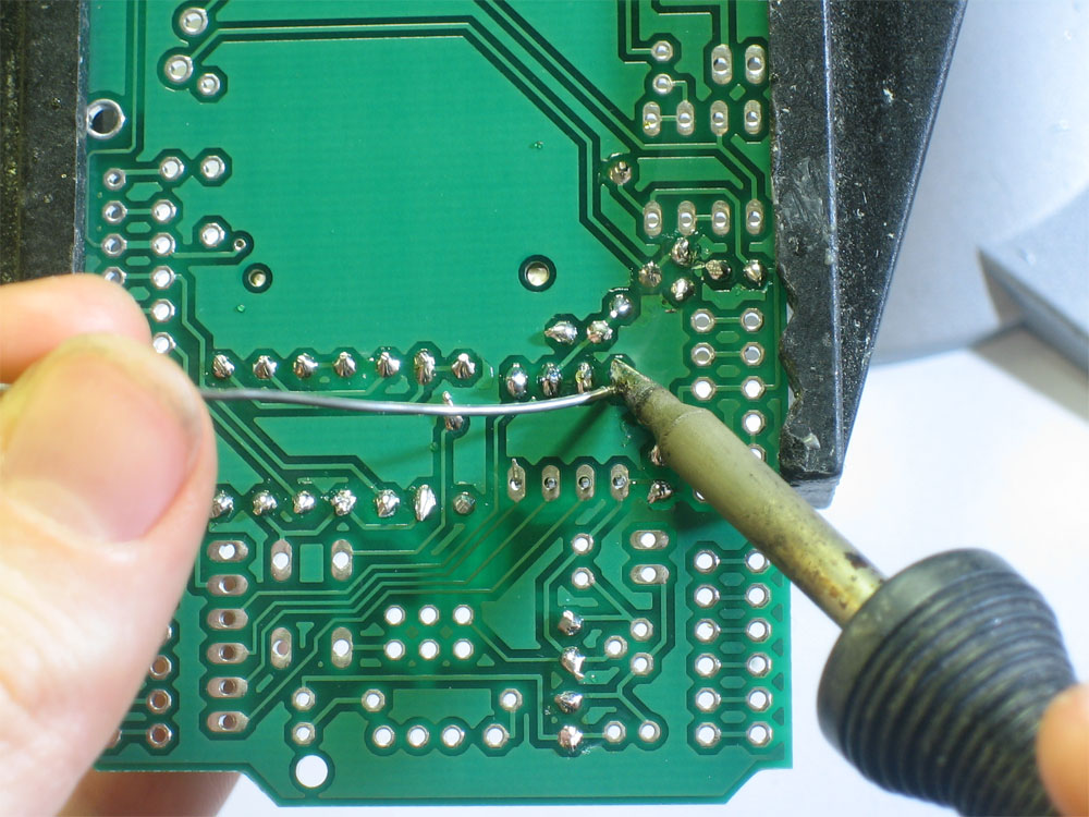
Pins 13, 12 and 11 are used to talk to the SD card and cant be changed. The rest of the pins, however, are more flexible. Still, for all the examples on the site we'll be using this wiring, so it is suggested to just go with this. You can use any sort of wire. Solder the jumper wires in place. |
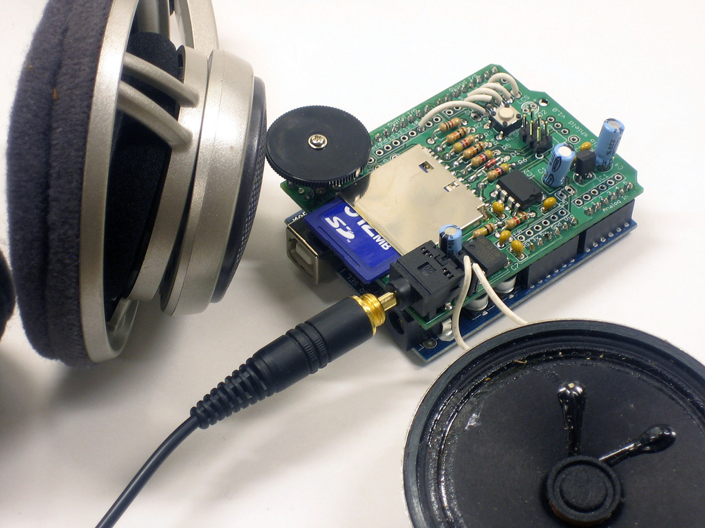 |
Hooray you are done! Now onto the user manual... |