Learn how to solder with tons of tutorials!
Don't forget to learn how to use your multimeter too!Some web browsers (basically, IE) do not like my website so much and load the photonotes slowly. So, if you are wondering where the rest of the instructions are, either wait a while and IE will eventually display it (below here). Or download Firefox/Safari which does not have this problem!

|
Check the kit to verify you have all the parts necessary |
 |
Get your space set up with a good light, a vice or "third-hand" tool, diagonal cutters, and a soldering iron/solder |
|
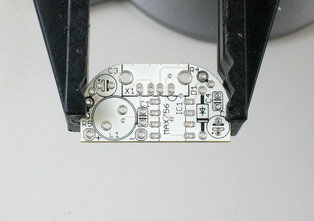
Put the circuit board in the vice, ready for soldering! |
  |
Place the two electrolytic capacitors C2 and C3 and the diode D1 in. Make sure you line up the white stripe on the diode with the white stripe in the picture on the circuit board. There are also white or black stripes with a minus sign on it on the capacitors, make sure they line up like in the picture to the left. If you're confused about the stripe, the side opposite to the stripe has a longer lead. When you put the parts in, bend the wire leads out a little so the parts stay up against the board when you turn it upside down to solder. |


 |
OK, now its time to solder. Make sure the iron is 650deg. Touch the tip at a 45deg angle so that its heating both the hole/ring and the wire lead, then touch/poke the solder in with your other hand. |
  |
Clip the leads with the diagonal cutters. Be careful that the leads don't fly at your face. Cut the wires right above where the solder joint tapers off. |


|
Place the two yellow ceramic capacitors C1 and C4, the power inductor L1 and the USB jack. The capacitors and inductor don't have a polarity, like the other capacitors and diode, so don't worry about putting them inbackwards.
Solder these parts in too. When soldering in the USB jack, make sure to put plenty of solder in the two large side holes: they are the mechanical connection for the jack. If you don't make a good solder joint (filling in the hole completely with solder) then the jack will eventually break! So do a good job. |


|
Clip the excess wires here too. Don't clip the USB jack leads: they're just the right size. |
 |
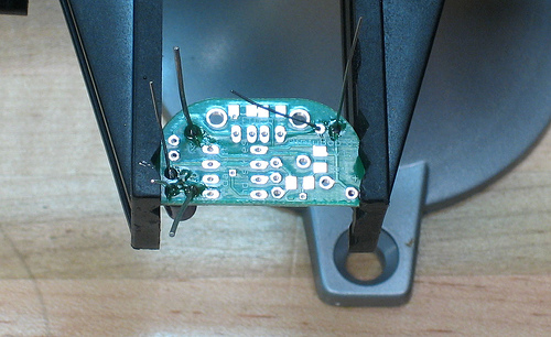
Place the 8 pin socket so that the notch is next to the jack, just like the silkscreened image on the PCB. Also put in the wires for the battery pack, make sure you don't mix them up! The red wire goes in the corner. |

 
|
Solder the pins of the socket, and the two wires. You might have to hold them against the board from underneath, if they seem to be slipping out. |

|
Bend the resistors as shown (pictures very soon) If you are using a Nano 2G (small metallic), Shuffle 2G (metal clip), Zune player, or if you are not getting your device to charge, try not installing R5 or performing the v1.1 R5 hack detailed below |
 |
OK, insert the MAX756 boost chip so that the little notch in the chip matches the notch in the socket. Make sure its well seated: press firmly, making sure all the pins are sliding into the socket straight. You're done! |
Some of the latest firmware for iPods has updated so that they don't play as nicely with MintyBoosts as they used to. Some devices (including Zunes) don't charge or seem to 'discharge' But not to worry, there is an easy fix! Try this:
R5 is normally a pull-down resistor (it is connected to negative/ground) but turning it into a pull-up resistor (connected to positive) makes everything OK. Luckily for us, v1.1 isnt too hard to adapt. The side of C3 closest to R5 is positive. Also the positive battery in is nearby. Both options are shown here, either will work so do whatever is easiest.


Soldering the top of a PCB is not as easy as the bottom, but it's not hard either. Cut the 'top' lead of R5 first, and then put a blob of solder where it will go and solder it on!
The USB specification says: USB1 maximum current is 100mA and USB2 is 500mA. By twiddling the 10K resistors you can get different charging currents. 100mA is the most efficient but maybe you want faster charging instead!
All of these tables assume that the pins are tied to the voltages through a ~10K resistor. Float means the resistor is disconnected
| iPod Mini | D- pin / R4 | |||
|---|---|---|---|---|
D+ pin R5 |
x | 0V | float | >3V |
| 0V | x |
x |
100mA |
|
| float | x |
x |
250mA |
|
| >3V | x |
250mA |
250mA |
|
| iPod Nano 1G | D- pin / R4 | |||
|---|---|---|---|---|
D+ pin R5 |
x | 0V | float | >3V |
| 0V | x |
x |
100mA |
|
| float | x |
x |
100mA |
|
| >3V | x |
250mA |
250mA |
|
| iPod Nano 2G | D- pin / R4 | |||
|---|---|---|---|---|
D+ pin R5 |
x | 0V | float | >3V |
| 0V | x |
x |
x |
|
| float | x |
x |
250mA |
|
| >3V | x |
100mA |
250mA |
|
| iPod Shuffle 2G (clip-on) | D- pin / R4 | |||
|---|---|---|---|---|
D+ pin R5 |
x | 0V | float | >3V |
| 0V | x |
x |
x |
|
| float | x |
x |
x |
|
| >3V | x |
x |
100mA (max) |
|
| iPod Color Video 30G | D- pin / R4 | |||
|---|---|---|---|---|
D+ pin R5 |
x | 0V | float | >3V |
| 0V | x |
x |
100mA |
|
| float | x |
x |
100mA |
|
| >3V | x |
100mA (?) |
100mA |
|
Mintyboost® is a registered trademark of Adafruit Industries