Table of Contents
Introduction
This tutorial is for our new TTL serial camera module with NTSC video output. These modules are a nice addition to a microcontroller project when you want to take a photo or control a video stream. The modules have a few features built in, such as the ability to change the brightness/saturation/hue of images, auto-contrast and auto-brightness adjustment, and motion detection.
Since it is a little confusing how this is both a snapshot and video camera, we'd like to explain it in detail now. The module was initially designed for surveillance purposes. Its meant to constantly stream TV-resolution video out of the Video pin (this is NTSC format) and also take commands from the serial port. The serial port commands can request that the module freeze the video and then download a JPEG image. So for example, normally its just displaying video to a security monitor. When motion is detected, it would take a photo and save it to a disk for later analysis.
The module is admittedly not extremely high resolution - the maximum image size it can take is 640x480 pixels. The reason for this is that it's meant for surveillance, not for nature photography. However, as far as we can tell, this is the best module on the market.
- Module size: 32mm x 32mm
- Image sensor: CMOS 1/4 inch
- CMOS Pixels: 0.3M
- Pixel size: 5.6um*5.6um
- Output format: Standard JPEG/M-JPEG
- White balance: Automatic
- Exposure: Automatic
- Gain: Automatic
- Shutter: Electronic rolling shutter
- SNR: 45DB
- Dynamic Range: 60DB
- Max analog gain: 16DB
- Frame speed: 640*480 30fps
- Scan mode: Progressive scan
- Viewing angle: 120 degrees
- Monitoring distance: 10 meters, maximum 15meters (adjustable)
- Image size: VGA(640*480), QVGA(320*240), QQVGA(160*120)
- Baud rate: Default 38400, Maximum 115200
- Current draw: 75mA
- Operating voltage: DC +5V
- Communication: 3.3V TTL (Three wire TX, RX, GND)
Sample images
Here are two example images, one of outside during a cloudy day, and one inside on a sunny day


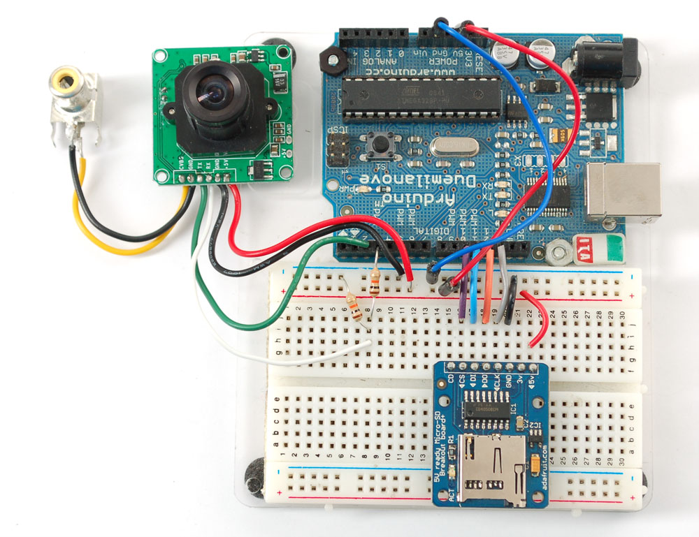
Wiring
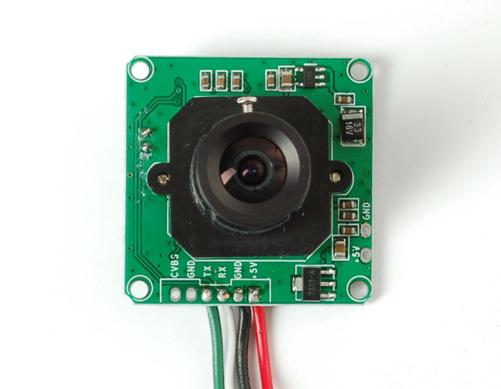
The module comes without any connector so you'll need to solder wires into the connection pads. The good news is the pads are not too close togehter (about 2mm) and you can use any stranded or solid-core wire.
If you aren't planning to use the video output abilities, you can use 4 wires. We will use red for the +5V pin, black for the Ground pin, white for the RX pin (data into the module) and green for the TX pin (data from the module)
If you'd like to get NTSC video out to connect to a TV or monitor, solder another black wire to the second Ground pin, and a yellow wire to the CVBS pin
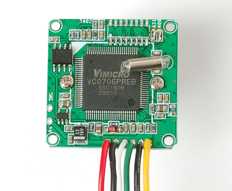

If you have the weatherproof version of this camera, it comes prewired with the following
- Red is connected to +5V in
- Black is connected to Ground
- Green is RX
- White is TX
- Yellow is NTSC Video signal out
- Brown is NTSC Video ground
Video output
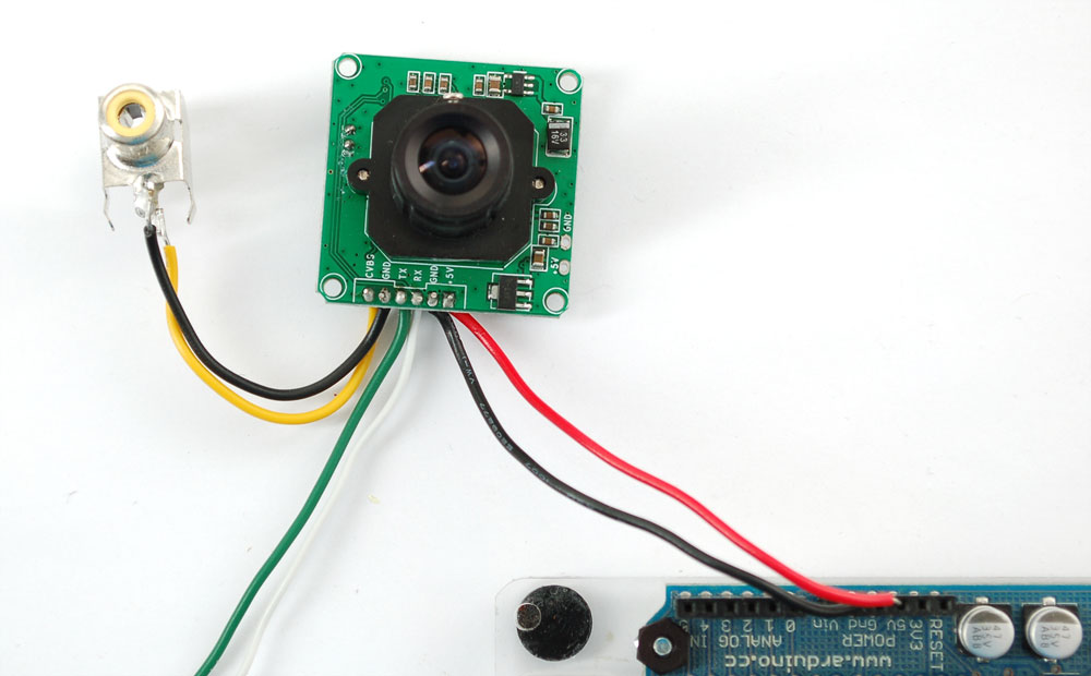
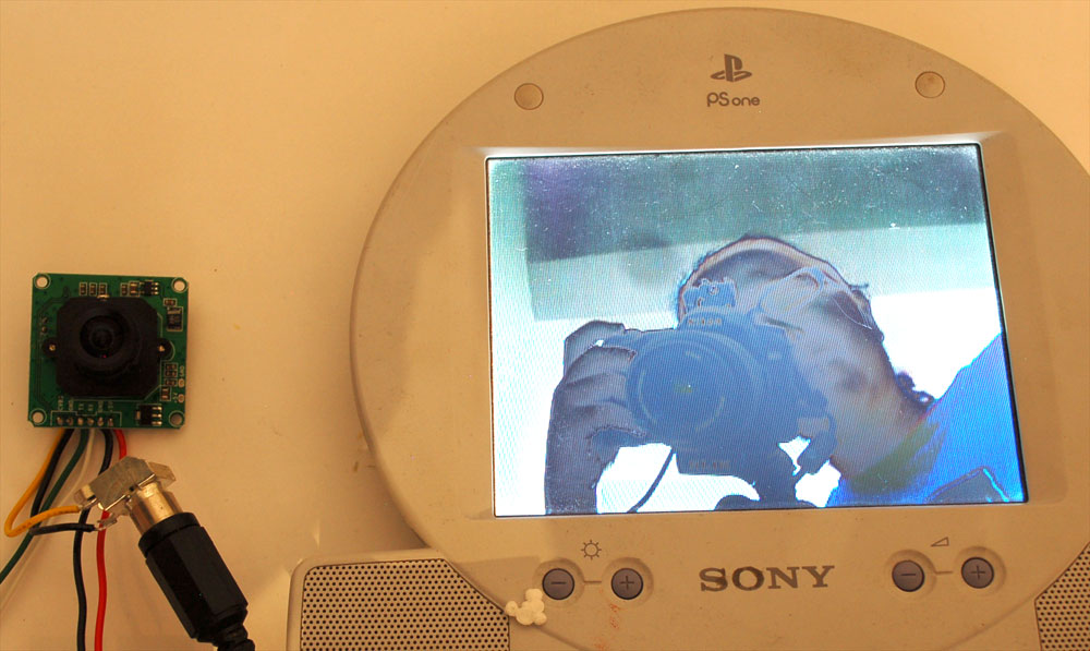
The quickest way to test out the modules is to use the NTSC video out connection. That way, when you adjust the hue/saturation/color/focus you can immediately see the results. Paired with the next section (using the Comm Tool), its the ideal method of introducing yourself to the module
Most TV's and monitors require an RCA jack or plug input. We just soldered a spare RCA jack to the camera, with black being the case ground and yellow signal. You can get RCA cables and accessories in any hobby/electronics shop like Radio Shack.
Unfortuantely it is not possible to change the camera from NTSC to PAL - its hardcoded by a pin soldered to the board and there's no easy way to extract it and change it (we tried!)
Plug in the NTSC cable to your monitor, and connect the red and black power wires to +5V supply - you should get color video output on the monitor immediately!
Using CommTool
To use the Comm Tool, a windows utility, we need to set up a serial link to the camera. There's two ways we suggest doing this. One is to use something like an FTDI friend or other USB/TTL serial converter. If you have an Arduino you can 'hijack' the serial chip (FTDI chip or similar) by uploading a blank sketch to the Arduino:
// empty sketch

void setup()
{
}

void loop()
{
}
And then wiring it up as follows:
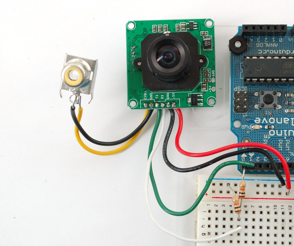
For the weatherproof camera, the white and green wires are swapped on some cameras! So please flip the white and green wires indicated if using the metal camera. Red should still be connected to +5 and Black to Ground
Note the 10K resistor divider, the serial data pins are 3.3v logic and its a good idea to divide the 5V down so that its 2.5V
Now download and install the VC0706 CommTool software (see below in the Download section)
Start up the software and select the COM port that the Arduino is on.
Then Open the port and click Get Version
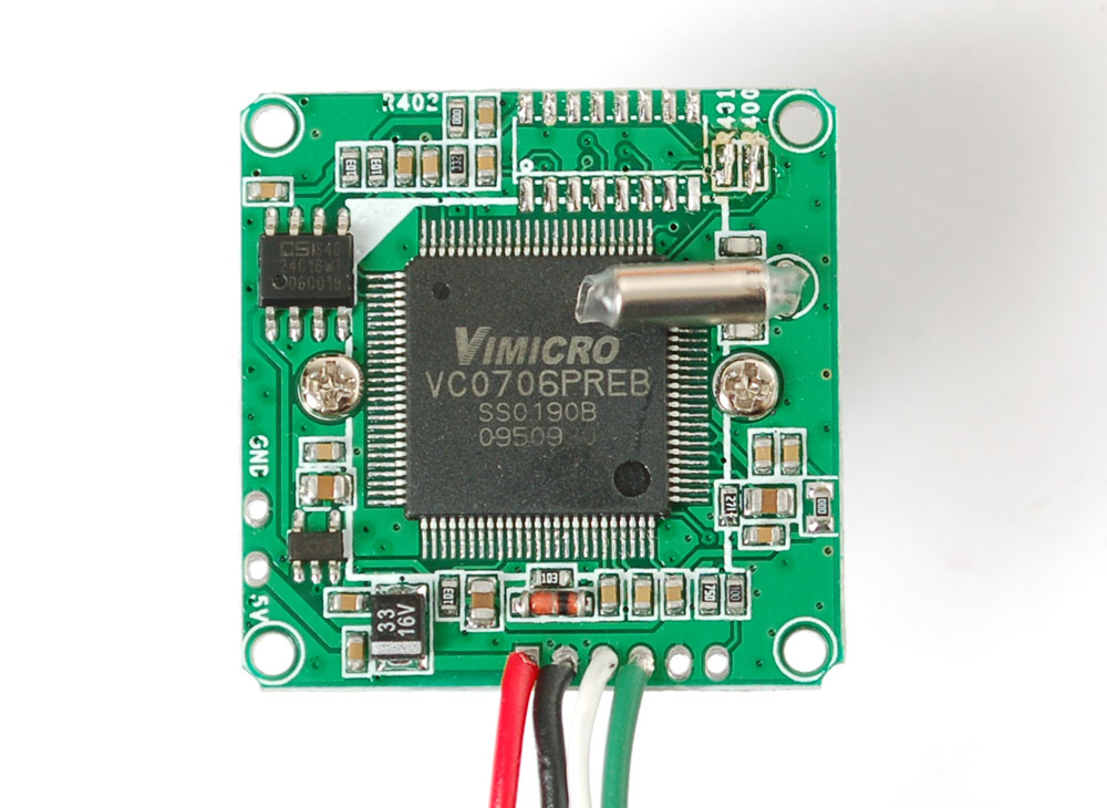
Note it says VC0703 - we don't know precisely why the DSP is programmed with a different number - its one of those mysteries! Still, you should get a response
The next button you should press is near the bottom FBUF CTRL.
This is quite a panel, but we can use this to get images directly from the camera which is good for debugging.
- Point the camera at something you want to take a photo of
- Click Stop FBuf to freeze the frame buffer
- Click Sel File to select the file to save the JPG as
- Next press Read (next to Sel File) to read the jpeg image off the camera
Thats it! You can now easily test reading camera images. To take another photo. Press Resume up at the top to have the video start up again. Then click Stop CFbuf when you want to snap another photo. Finally you can select the Compression Ratio which will improve or degrade the image quality but also change the image transfer time. There's no way to change the image size from this program (easily) but we can do it using the Arduino sketch so just try it out here to start.
There's only a few other things we suggest doing with this software. One is changing the baud rate. By default the baudrate is 38400 baud. This is a pretty good rate but you can of course change it by going to the Comm Config panel. You want to change tbe MCU UART BPS part - not the High-Speed UART part. Be sure to test the baud rate using your set up after you change it. Its easy to close the COM port and reopen it here rather than wrangling with your microcontroller
The only other thing we suggest checking out is the Image Property button, which will let you adjust settings for the camera, we bumped up our saturation a bit to get better images. Dragging the sliders will make the video output change immediately so this is a handy place to get a TV connected up so you can check out how it works
There are many options for this software, here's what we think of the other buttons. Personally, we don't suggest going in to any of them unless you really need to.
- Config - see above
- Get Version - see above
- R/W Data - this is for writing raw data to the DSP chip processor. Don't do this unless you're sure you know what you're doing since it will mess with the camera's ability. Even we don't know what it would be good for
- Color Ctrl - this is for selecting Color or Black&White or Auto select (probably based on lighting conditions). You probably want to keep it at Auto
- Mirror Ctrl - we think this is so you can flip the display (if its bouncing off a mirror)
- Power Ctrl - this is for testing the power down mode, and it seems like you might be able to have it auto-power down when there's no motion.
- Timer Ctrl - there is an RTC built into the DSP which you can set, however there's no battery backup so if power is lost the RTC will be reset so we don't think its terribly useful
- AE Ctrl - this is for controlling the auto-contrast/brightness. By default its set to auto-select for indoor or outdoor use. Probably best to leave it as is
- Motion Ctrl - this is for the motion detection system. You can tweak the settings and also test it. We have an Arduino sketch for interacting with the motion detection system. By default it works pretty good but you can super tweak it out if you want to.
- OSD Config - The protocol sheet and this seem to imply you can do on-screen-display but after much time spent on it, we determined its not activated somewhere in the DSP. We've never seen a VC0706 camera that could do it. :(
- Image property - see above
- Gamma - this is for more precise gamma control of the CMOS sensor. It seems to be preset to be OK but you can mess with this if you'd like
- SPI Flash - for reading/writing to the SPI storage? Not sure if its a good idea to mess with this
- Other Ctrl - for playing with the DAC? No idea what this is for.
- Up/Down Load - this is for reading and writing to the flash probably to upload new DSP code. We dont suggest messing with this
- System Reset - does a reset of the module. Press this if its not responding
- FBuff Ctrl - see above
- Zoom Ctrl - The module has built in 'Pan Tilt Zoom' ability BUT its for video only and wont affect photos snapped. You can play with the PTZ here, its pretty basic but could be useful for someone
Microcontroller Wiring
Next up, we will wire the camera to our microcontroller (in this case an Arduino). This is pretty similar to the above except we will be using two digital pins and a software serial port to talk to the camera. To save images, you'll need some sort of external storage like our microSD breakout board.
Connect up the camera like this:
For the weatherproof camera, the white and green wires are swapped on some cameras! So please flip the white and green wires indicated if using the metal camera. Red should still be connected to +5 and Black to Ground
We suggest testing the microSD card first. Check out our microSD breakout board tutorial and verify that you can read from the card by listing the files. Once you have verified the microSD card wiring, you can come back here and install the VC0706 camera library.
Visit the Github repository here. To download. click the DOWNLOADS button in the top right corner, rename the uncompressed folder Adafruit_VC0706. Check that the Adafruit_VC0706 folder contains Adafruit_VC0706.cpp and Adafruit_VC0706.h Place the Adafruit_VC0706 library folder your /libraries/ folder. You may need to create the libraries subfolder if its your first library. Restart the IDE.
If you're using Arduino v23 or earlier, you'll also need to install the NewSoftSerial library. Download it by clicking this link and install it as you did the Adafruit_VC0706 library. Arduino 1.0 has this built in now (called SoftwareSerial)
Taking a snapshot
OK now you're finally ready to run the snapshot demo. Open up the Arduino IDE and select File→Examples→Adafruit_VC0706→Snapshot sketch and upload it to the Arduino. Open up the serial monitor and you can see the sketch will take a 640x480 photo and save it to the microSD card. You can then pop the card into your computer to see the JPG file
There are a few things you can change once you get it working. One is changing the pins the camera uses. You can use any two digital pins, change this line:
// This is the camera pin connection. Connect the camera TX
// to pin 2, camera RX to pin 3
NewSoftSerial cameraconnection = NewSoftSerial(2, 3);
You can also change the snapshot image dimension to 160x120, 320x240 or 640x480 by changing these lines:
  // Set the picture size - you can choose one of 640x480, 320x240 or 160x120
  // Remember that bigger pictures take longer to transmit!

  cam.setImageSize(VC0706_640x480);        // biggest
  //cam.setImageSize(VC0706_320x240);        // medium
  //cam.setImageSize(VC0706_160x120);          // small
Simply uncomment the size you want, and comment out the others. Bigger pictures will take longer to snap, so you will want to think about how fast you need to grab data and save it to the disk
Detecing motion
A neat thing that the camera has built in is motion detection. It will look for motion in the video stream and alert the microcontroller (by sending a serial data packet) when motion is detected. IN this way you can save a bit of cash and skip on having a PIR sensor (although a PIR sensor will be better at detecting warm mammalian things)
Load up the File→Examples→Adafruit_VC0706→MotionDetect sketch and upload it to the Arduino. It will take a photo immediately because it just turned on. Then wait a few minutes and wave you hand in front of the camera, it will take another photo.
You can turn motion detection on or off by calling setMotionDetect()
  //  Motion detection system can alert you when the camera 'sees' motion!
  cam.setMotionDetect(true);           // turn it on
  //cam.setMotionDetect(false);        // turn it off   (default)
You'll need to 'poll' the camera to ask it when motion is detected, by calling motionDetected()- it will return true if motion was recently detected, and false otherwise.
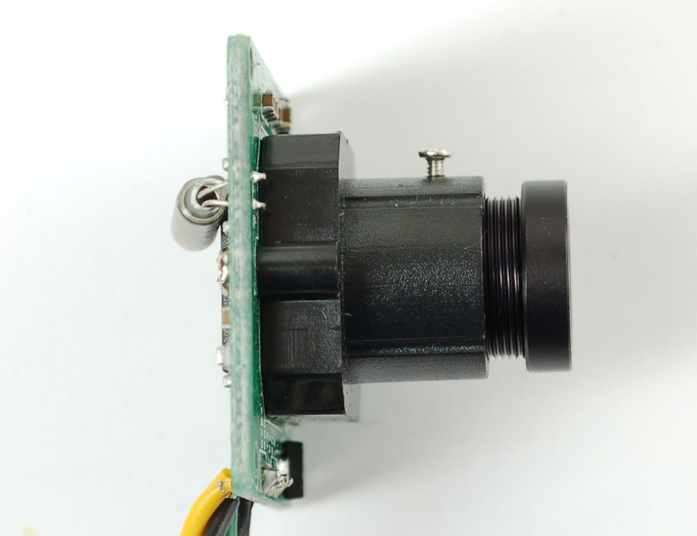
Adjusting the manual focus
One last thing, the camera modules use a manual focus system - there's no auto focus. This can be good or bad. The camera comes with a far depth of focus which is good for most stuff. If you want to change the focus, we strongly recommend plugging it into a video monitor as shown above so you can see exactly how the camera focus looks. You can then lock the focus with the set screw
Download
