Table of Contents
Voltage Controlled Filter
Schematic Overview:VCF
Inputs:
VoltageControlledOscillator Audio In, EnvelopeGenerator Envelope In, EnvelopeGenerator Accent
Outputs:
VoltageControlledAmplifier Audio Out
There are 4 major sections to the Tb303's VCF. It is a unique 4 pole diode ladder filter (the diode ladder was an invention of Bob Moog's) which gives the response of a 3 pole filter. You might be wondering however, where all the diodes went. Apparently you can wire up transistors to act like diodes, and this is what is going on here. You can view the Patent for Bob Moog's ladder filter here: moog_pat3475623.pdf
(Transistors are apparently more versatile than diodes and whenever designing a diode ladder VCF, use transistors. matching is very important, that's all I know)
This filter has the property where resonance is increased, the peak stays at the same volume and the passband is reduced in volume. This is contrasted with the state variable filter where the passband retains its volume, and the peak gets louder.
The output is taken from the VoltageControlledOscillator switch, and fed to R62 and C17, AC coupling the filter (VCO has DC offset). Then it is sent to the left base of Q12, and also attenuated to 5.333V via R68, R70, R98 and C16, and send to the right base of Q12. The common emitter of Q12 serves as a (current based) control for the cutoff frequency, and this is where the EnvelopeGenerator is input, both for the Env Mod values, and the Accent.
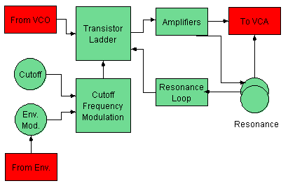
Block Diagram
Transistor Ladder
The transistor ladder itself consists of 3 good poles. Each pole consists of 2 2sc536f transistors and a 0.33uF capacitor. The Transistors are Q13, Q14, Q15, Q16, Q17 and Q23, and the caps C19, C24 and C26.
There is a 4th pole to the filter, which might be the combination of Q12 and its capacitor C18. Due to a design flaw, the 4th pole is staggered up an octave above the rest, which makes it respond more like a 3 pole lowpass, rather then a 4 pole. This design seems to be that the value of C18 is 0.18 uF, instead of 0.33uF like the other poles.
Another "flaw" might be that the original Moog ladder filter had resistors connected from the common base of Q22, all the way down the ladder, and eventually connected to ground. Where as the TB303 and x0xb0x uses a single resistor, and connects that to a capacitor and then ground.
Here is a link to a Moog filter schematic and board (to build your own!) for comparison: http://dropmix.xs4all.nl/rick/Emusic/Moog/
Amplifier
Q19, Q20, Q21 and Q22 all seem to be involved in the amplification of the now-filtered signal. The emitter of Q19 is sent to VR4 and the resonance feedback loop.
Resonance Feedback
The Resonance Feedback is also the VCF output. There are actually 2 outputs which are combined before entering the VoltageControlledAmplifier. One output is sent directly to the VCA, and goes through a .01uF Cap and 220K resistor. The other output goes through VR4 (resonance) and sent to the VCA, through a .01uf Cap and 100K resistor.
The signal from VR4 is also fed back into the VCF circuit. First it is attenuated (or amplified?) by the 5.333 Volts, and R66, R67, R99 and C22. It is fed into the base of Q18 where Collector of Q18 is connected to the +12 V. (this may also be an amplifier?) The signal is finally sent to the right hand base of Q12, making its way through the Transistor Ladder again.
Cutoff and Envelope Modulation
(… more to come …)
From the service manual
… With bad engrish and all …
In the conventional VCF configuration, envelope modulation voltages applied to the modulation control voltage input of VCF rise from a fixed potential to their values regardless of shape and amount of envelope and fall back to the same potential. In this setup, an attempt to deepen envelope modulation is increment of control voltage in one direction, only to open up filter. Resultants are: higher the control voltage input, longer the period of time cutoff point travels through higher frequency range in which significant aural sound characteristic changes do not occur, whereas notes are brightened.
To compensate for the limitation this impose, there is a gimmick in the TB-303 VCF circuit. The Q9 has a key role in this arrangement. It develops bias for Q10 and Q11 to set initial cutoff point at the center of frequency range. Within the range even a small amount of voltage change can create a appreciable modulation. Rotating wiper of VR5 closer to terminal increases Env Mod voltage being fed to base of Q10 while changing the bias which in turn lowers VCF cutoff frequency. This is equal to turning CUTOFF knob counter clockwise and, since Q10 and Q11 in combination convert control voltage to the current in anti-log fashion, the cutoff point stays in an effective frequency range for the most portion of envelope sweeping duration.


