 |
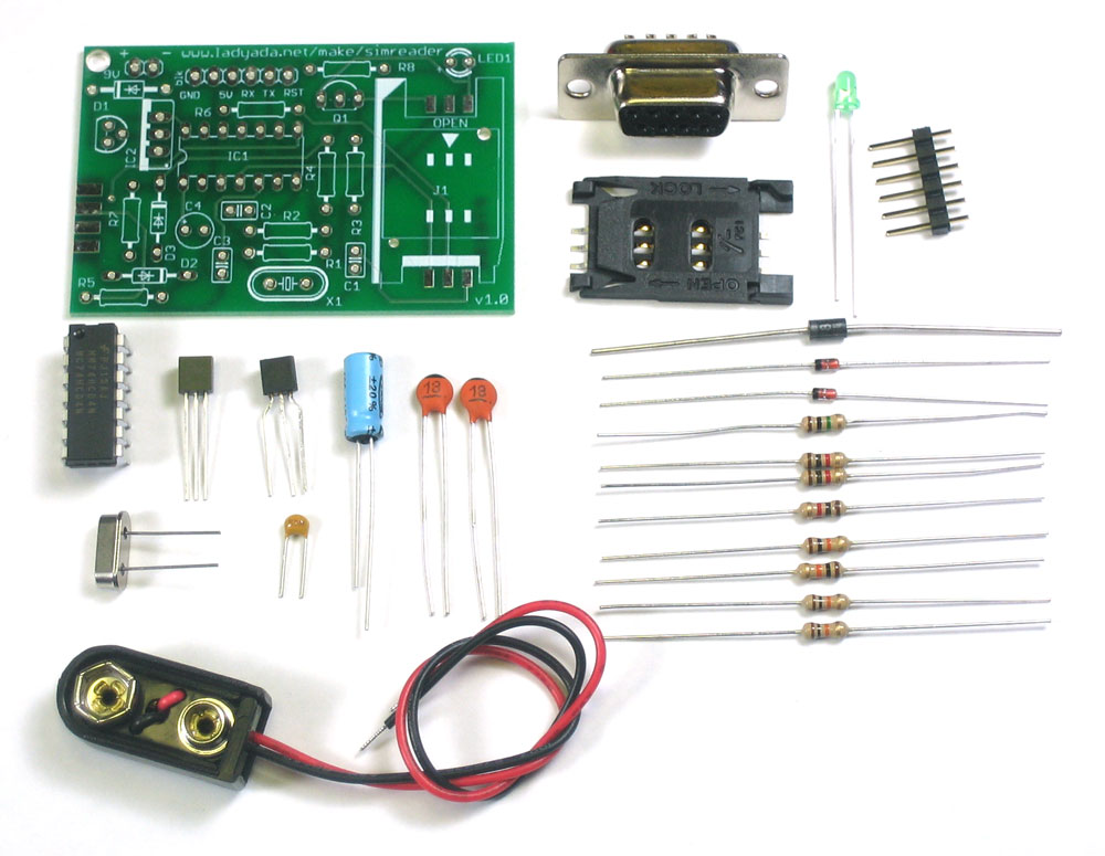
Check all your parts against the bill of materials
|
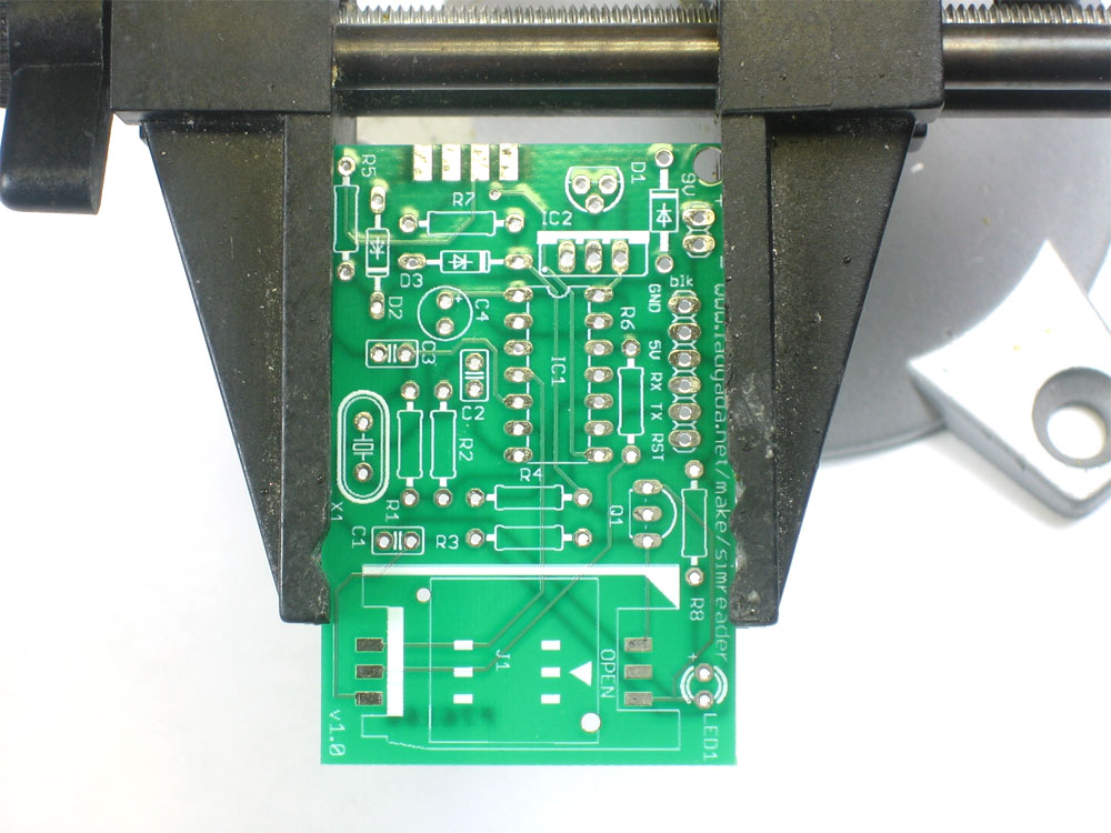 |
Get ready by placing the PCB in a vise Heat up your soldering iron to 700deg F, clean the tip and make sure your sponge is wet Lets go! |
|
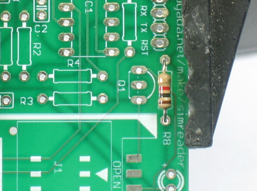
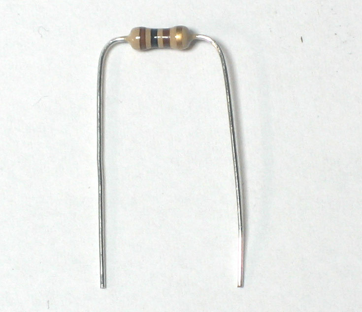
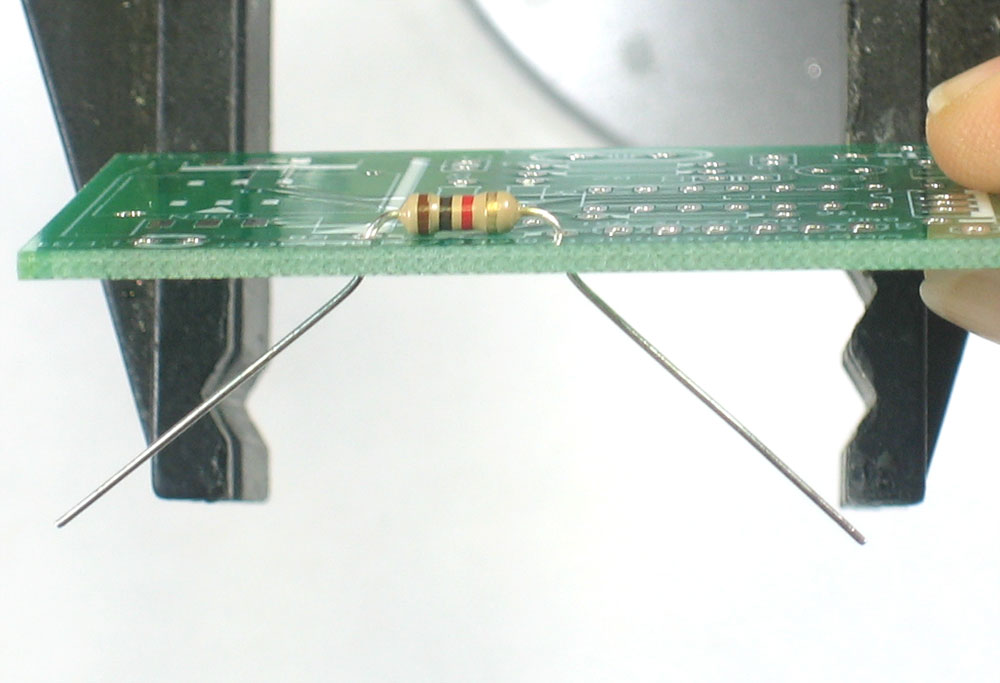
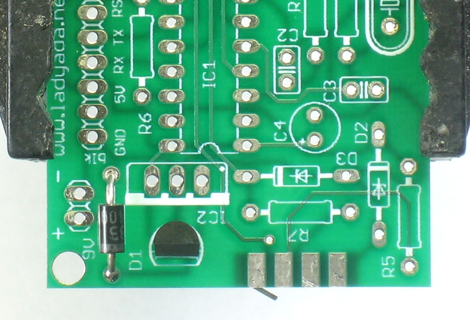
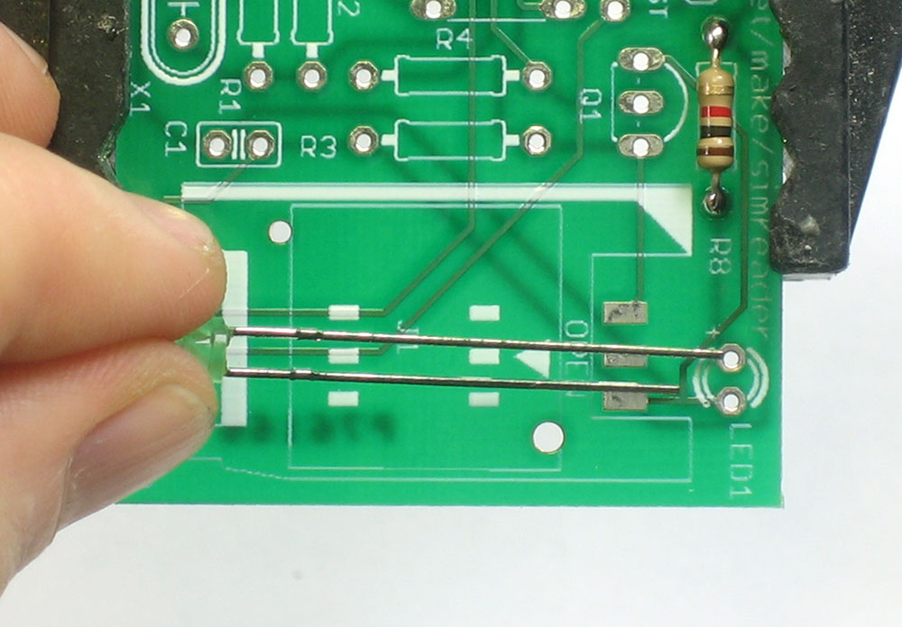
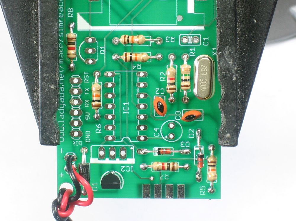
First thing we will place is R8, a 1.0K resistor (brown, black, red gold). This resistor sets the brightness of the indicator LED. Bend the resistor into a staple as shown, and slip it in. (The second photo at left shows a 100 ohm resistor but just ignore the stripes) Place the resistor in the location marked R8. Resistors do not have polarity which means you can put it in 'either way' and it will work just fine. Bend the wire legs out so that the resistor sits flat against the PCB. |
|
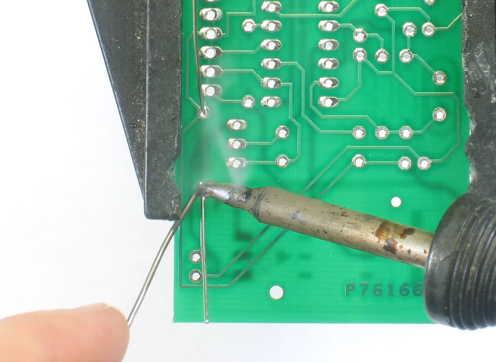
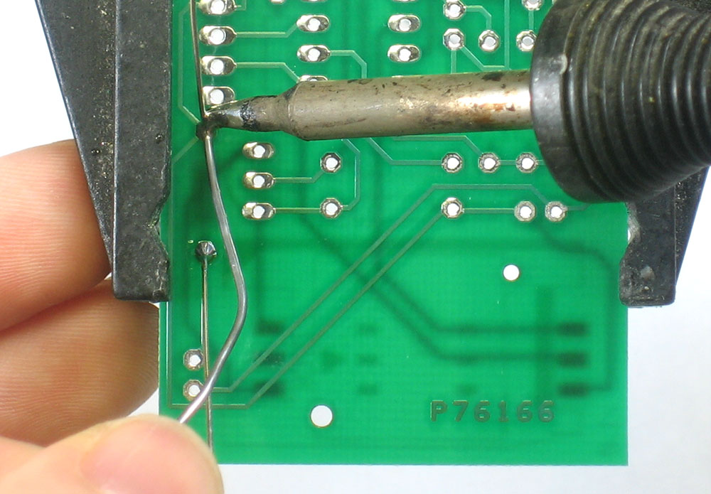
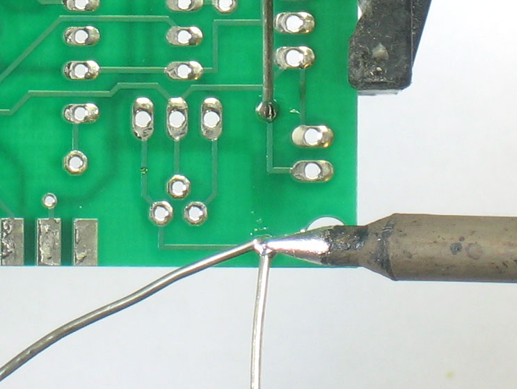
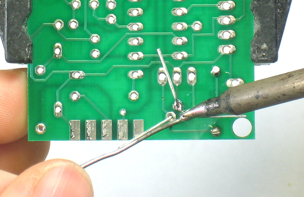
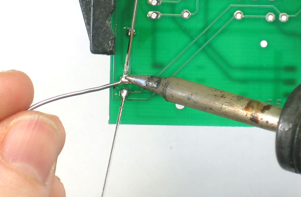
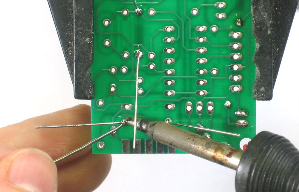
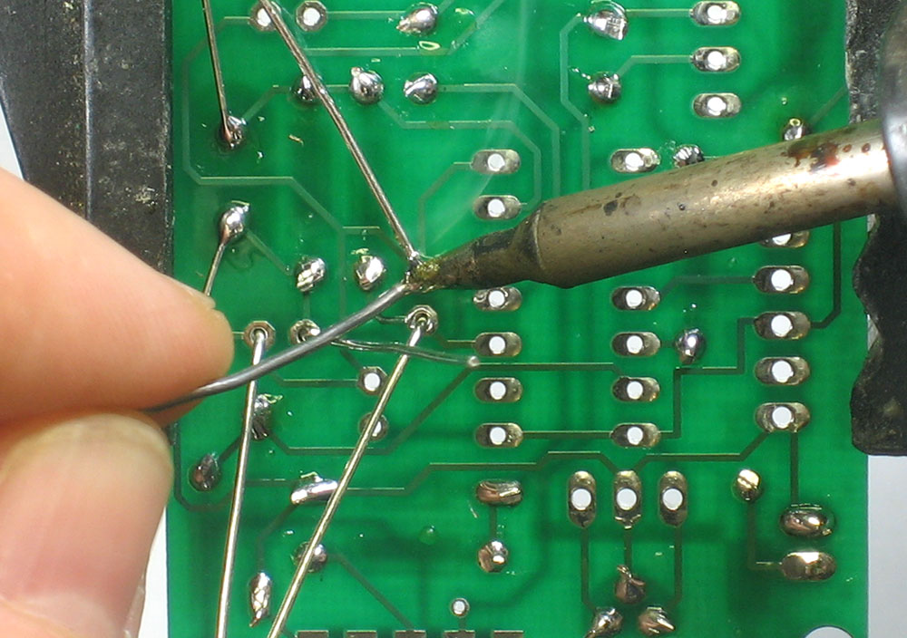
Turn the PCB over. Using your soldering iron tip, press and heat both the pad (the silver ring around the hole) and lead (wire) at the same time for 2 or 3 seconds. Then poke the end of the wire into create a nice solder joint. Do this for both leads. |
|
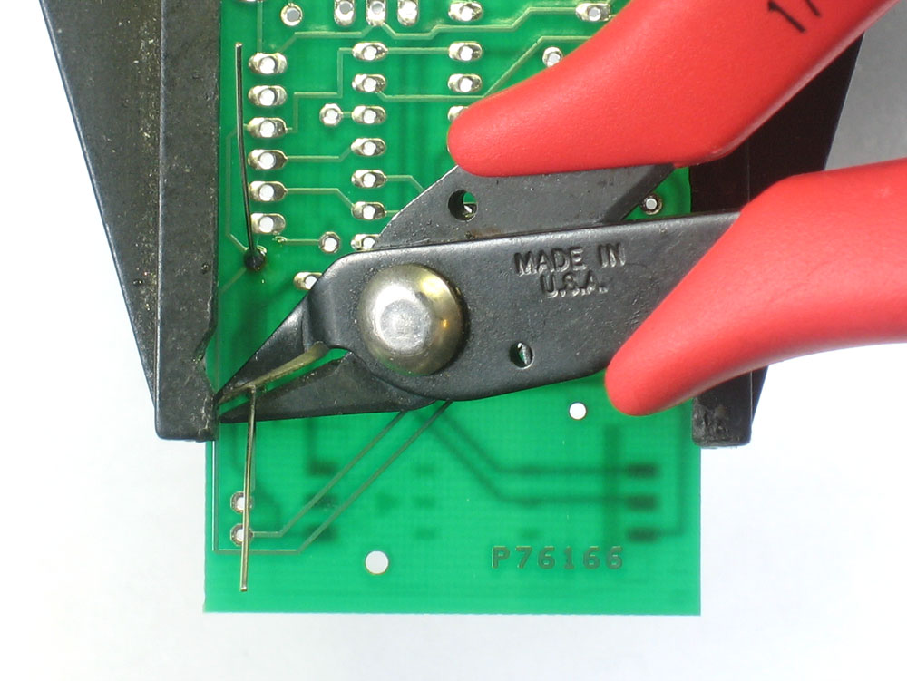
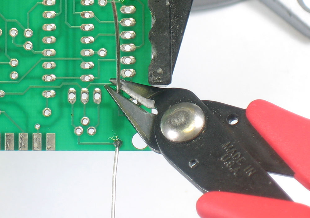
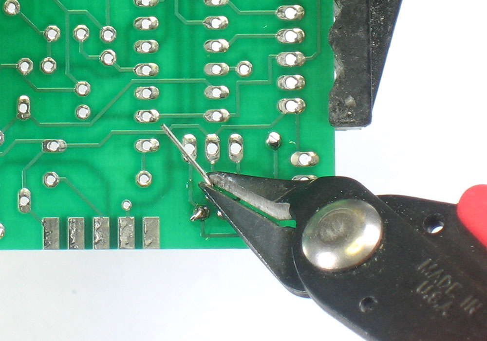
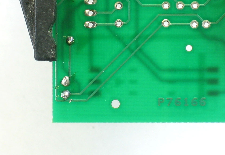
Using your diagonal cutters, cut off the long leads just above the solder joint. |
|
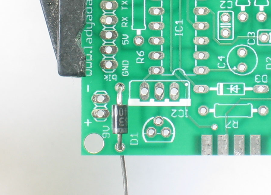
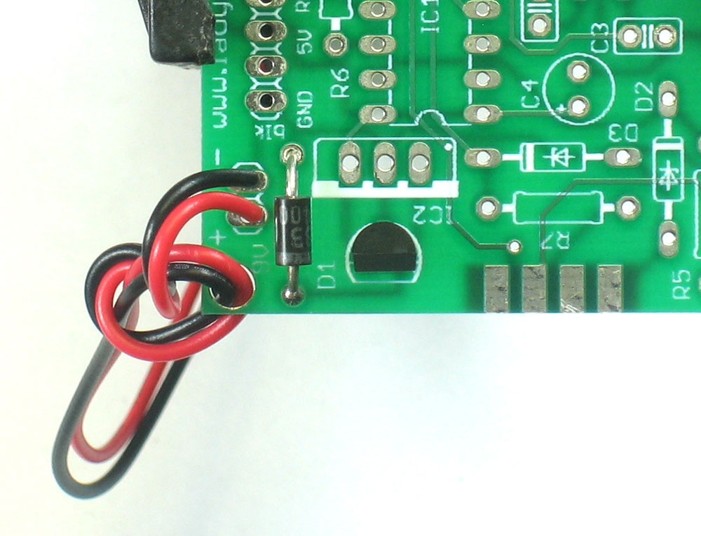
Next is the 1N4001 protection diode D1. This protects the SIM card and voltage regulator from accidentally connecting the 9V battery backwards. Diodes, unlike resistors, are polarized: they only let current through one way. Thus it is very important that the diode is placed correctly. Bend it into a staple like the resisor but make sure that the white stripe on the end of the diode matches the white stripe in the silkscreen image. |
|
Solder and clip the diode |
|
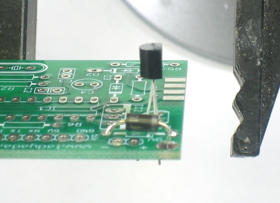
Next is the 7805 (or78L05) 5V regulator IC2. This is a small chip that converts the 9V battery power to a steady 5V. This is necessary because SIM cards can be destroyed by connecting 9V power to the contacts. The 5V regulator must be placed a certain way. Make sure the flat side of the regulator matches the flat side of the silkscreen image. Bend the middle leg back a bit and then press it down so it sits a few mm above the PCB |
|
To keep it from falling out, bend the leads out. Then solder and clip all three leads |
|
Next is the indicator LED (Light Emitting Diode) LED1. This LED is connected directly to the 5V line so that it is easy to tell if there is power to the board. LEDs are diodes too, and only work if placed correctly. Make sure the longer lead of the LED goes into the hole marked with a + |
|
Solder and clip the leads of the LED |
|
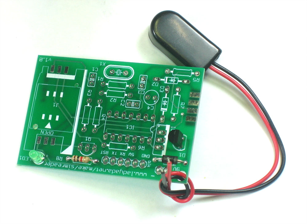
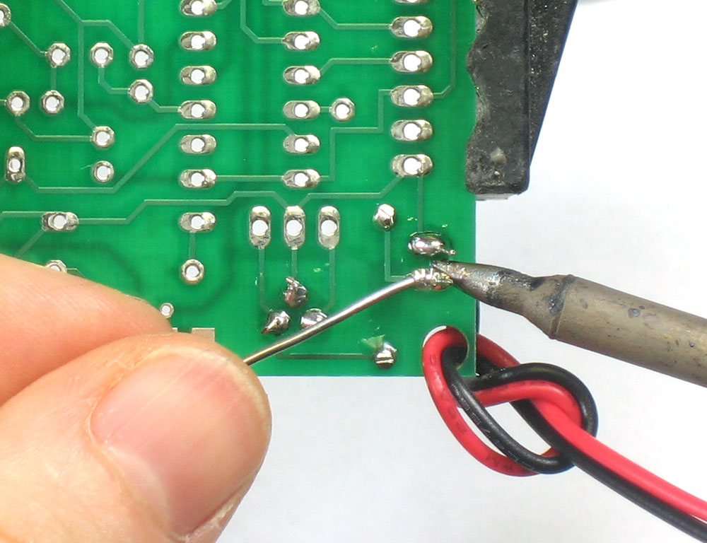
Next is the 9V battery holder. This will provide power to the circuitry. thread the two wires through the hole in the corner and tie them in a knot. This will act as a strain-relief which will keep the wires from snapping off. Then put the red wire into + and the black wire into - Turn the PCB over and solder in the two power wires. |
 |
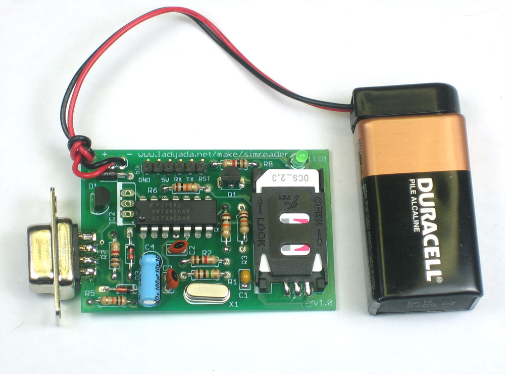
Tighten up the knot so that it is secure and connect a 9V battery. The green LED should light up, inducating that the 5V power supply is working well. |
|
|
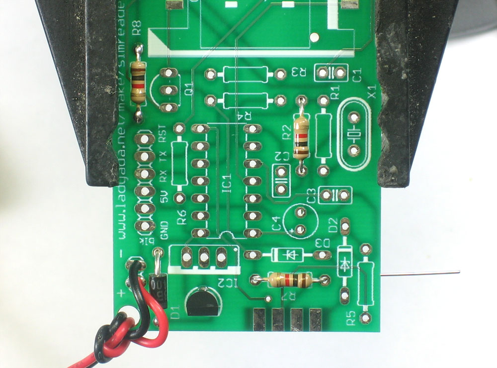
Next lets solder in the other two 1.0K resistors, R2 and R7 |
 |
Next are the four 10K resistors R3, R4, R5 and R6. |
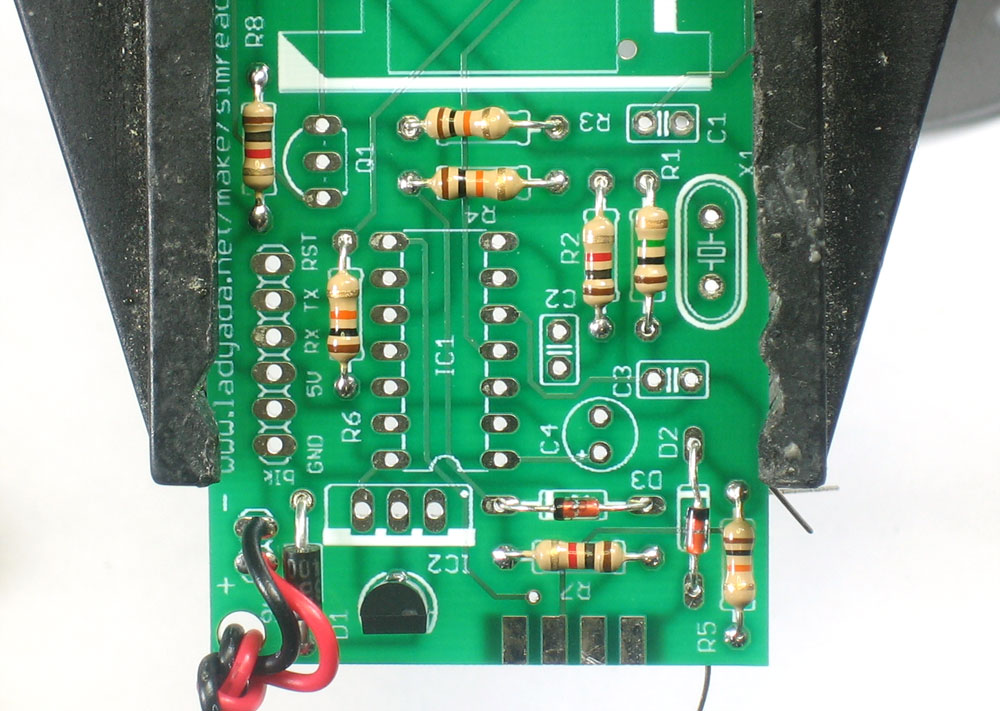 |
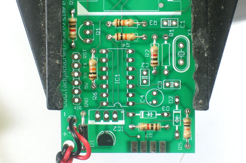
Next place and solder the 1Meg resistor (Brown Black Green) R1 and the two 5.1V zener diodes D2 and D3. The resistor is used in the feedback circuit for the crystal, to keep it oscillating. The two zener diodes are used to regulate the serial data coming from the serial port. The diodes will block the +-10V signal and keep it between ground and 5V, which is ideal for the SIM card. Like the power protection diode, these diodes must be inserted correctly to function. Make sure the black stripes on the diodes match the stripes on the silkscreen. |
|
Next is the 3.57 MHz crystal X1. This crystal is necessary to generate a clock for the SIM card microprocessor. The baud rate at which it communicates is proportional to the crystal speed. For this crystal value, the baud rate is 9600 bps. The crystal needs 2 18pF ceramic capacitors C2 and C3 for stability. They are not polarized so place them in either way. |
|
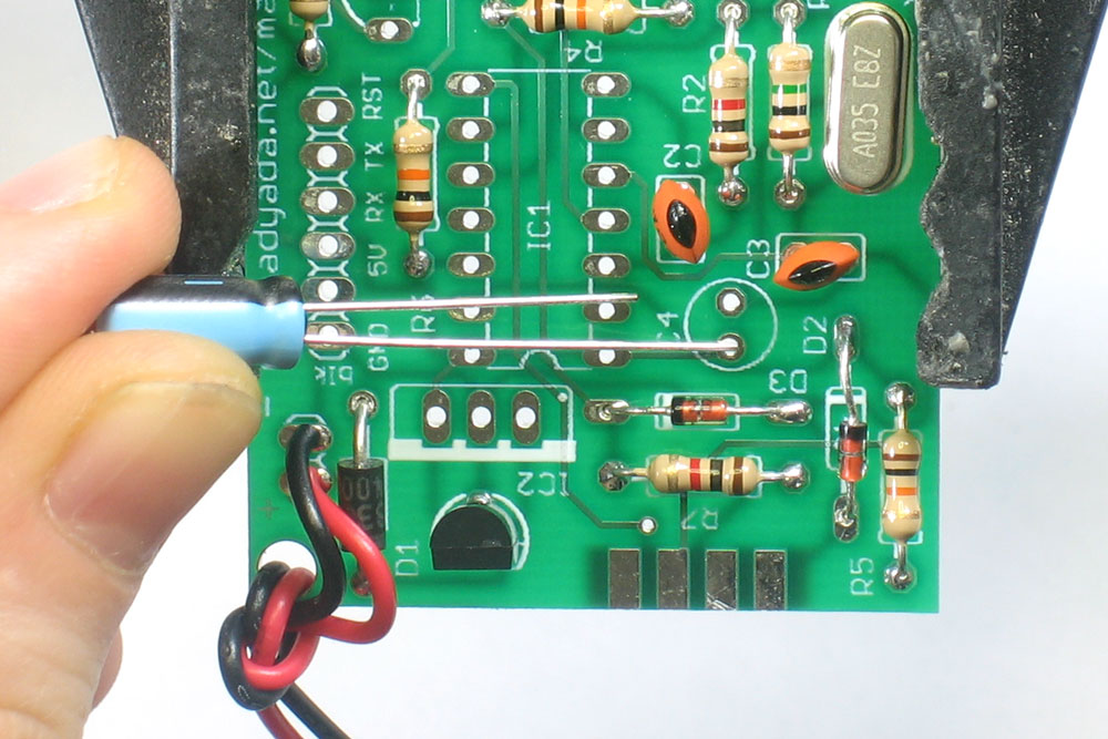
The electroytic capacitor C4 provides coarse stability and smoothing to the 5V supply. Electrolytics are polarized so make sure the long lead goes into the hole marked with a +. You can bend the capacitor over a bit so that it doesn't stick out so much. |
|
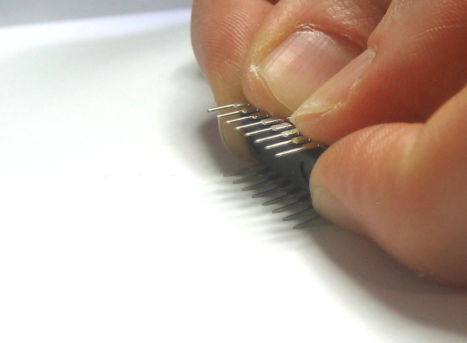
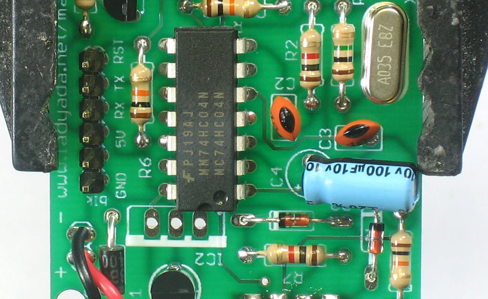
Next is the 74HC04 hex inverter IC1. This chip has multiple purposes. One is to invert the signal from the serial port (which is +-10V), and buffer them to be exactly 5V. It also is used as the feedback driver which causes the crystal to oscillate. The pins of ICs are a little skewed when they come from the factory, so they need to be bent in just a tiny bit, to be parallel. Grip the chip from the ends and use a table. Then carefully slide the chip so that the notch in the chip matches the notch in the silkscreen. Make absolutely sure this is correct because once its soldered in its nearly impossible to repair! Also place in the ceramic capacitor C1, which provides fine stability and smoothing to the 5V supply. It is placed near the SIM card holder to make sure the SIM card has the cleanest supply possible. Finally, place the NPN transistor Q1, which is what allows the 2 receive/transmit signals to share a single pin on the SIM card. |
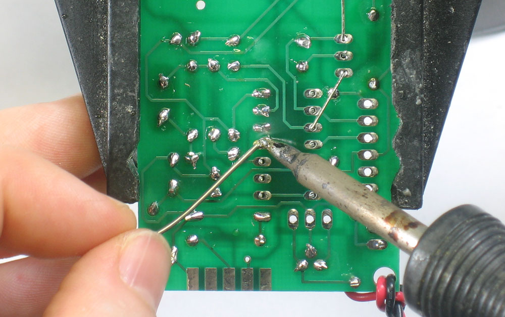 |
Solder each pin of the chip, making sure that the solder joints are shiny and smooth. The pins are quite short so they don't need to be clipped. |
|
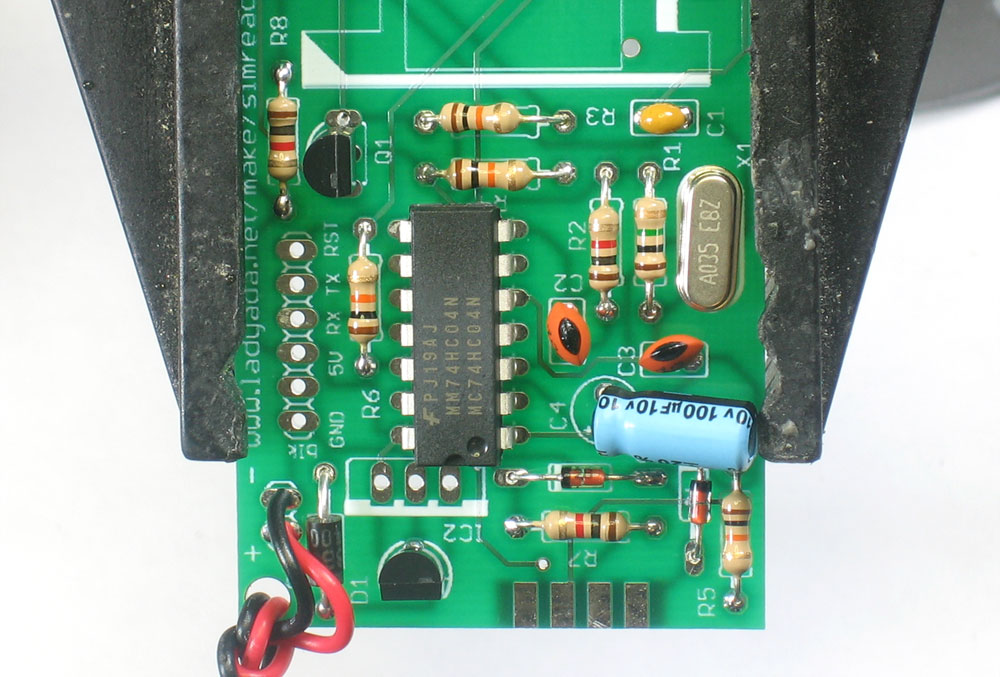
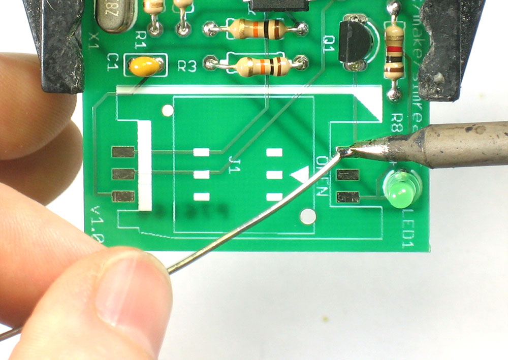
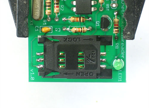
Using the tip of the soldering iron, heat up one of the SIM holder pads and melt a small bump of solder onto it. Then, hold the SIM card holder in one hand while reheating the pad with the other, slide the holder so that the corresponding pins align with the pads.once the pad has remelted and joined the pin and pad, remove the soldering iron. Double check that the notched corner of the SIM holder lines up with the silkscreen as shown. The SIM holder might have extra pins, just ignore these and solder in the 6 that have pads underneath them! |
|
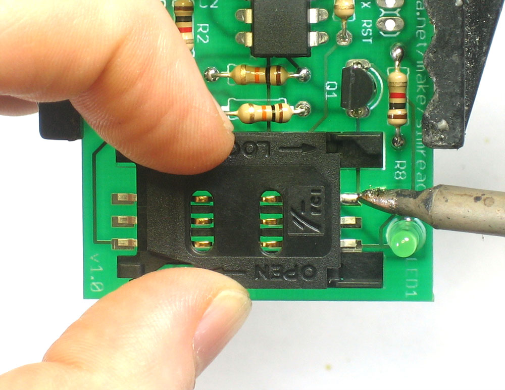
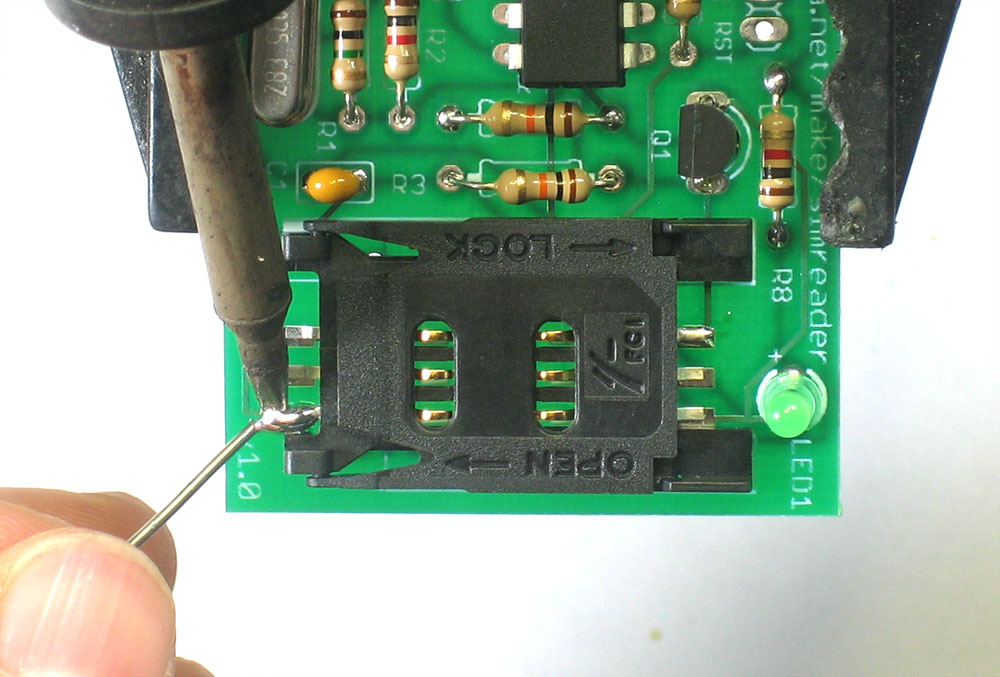
Now solder the rest of the pins. Heat up the pad and pin together and then poke a small bit of solder in |
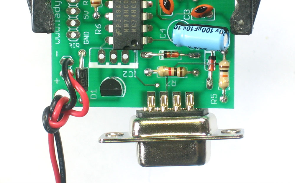 |
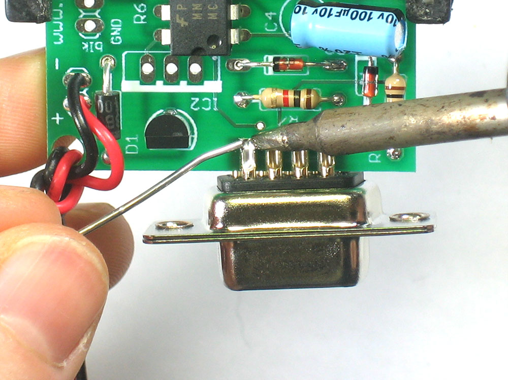
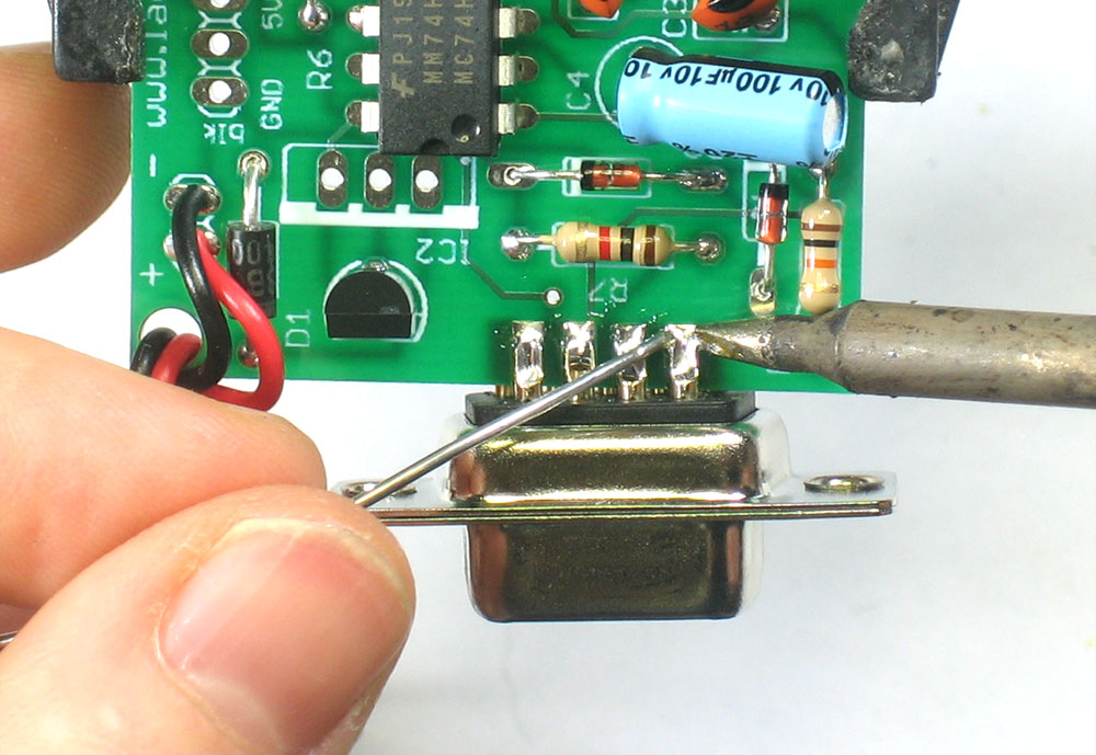
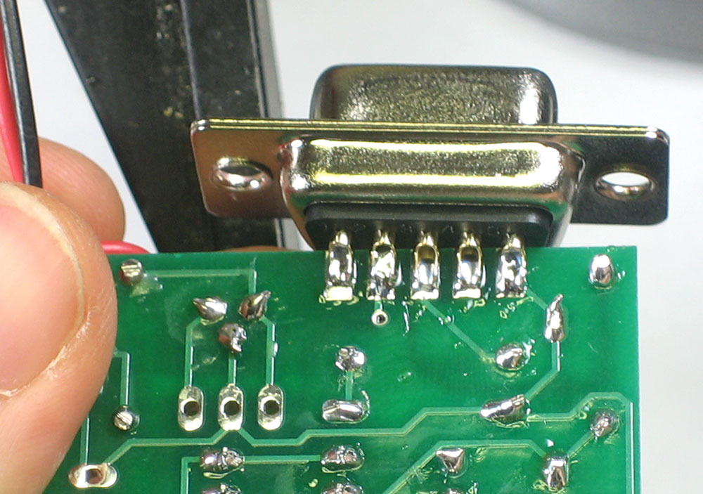
Slip the female DB-9 connector onto the end, it will sandwich the PCB nicely. This is the serial port that will connect to a computer. Make sure the pins and pads line up, one side is 5 pads and the other is 4 |
|
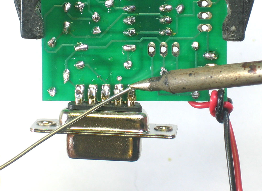
Solder each of the 9 pads, making sure to heat up the pad as well as the pin so that the solder goes between the two and doesn't just fill up the pin's cup. |
|
Finally, if you're planning to use an FTDI cable to connect to the board, solder in the 6-pin male header. Make sure the long pins point up. If, rather, youd like to plug it into a breadboard, make the long pins point down. |
 |
You're done! Now go read the User Manual |