These instructions are for v1.1 and v1.0 ONLY
|
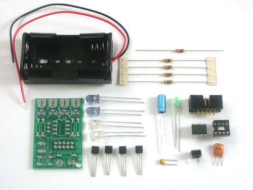
Check the kit against the parts list to verify you have all the parts necessary |
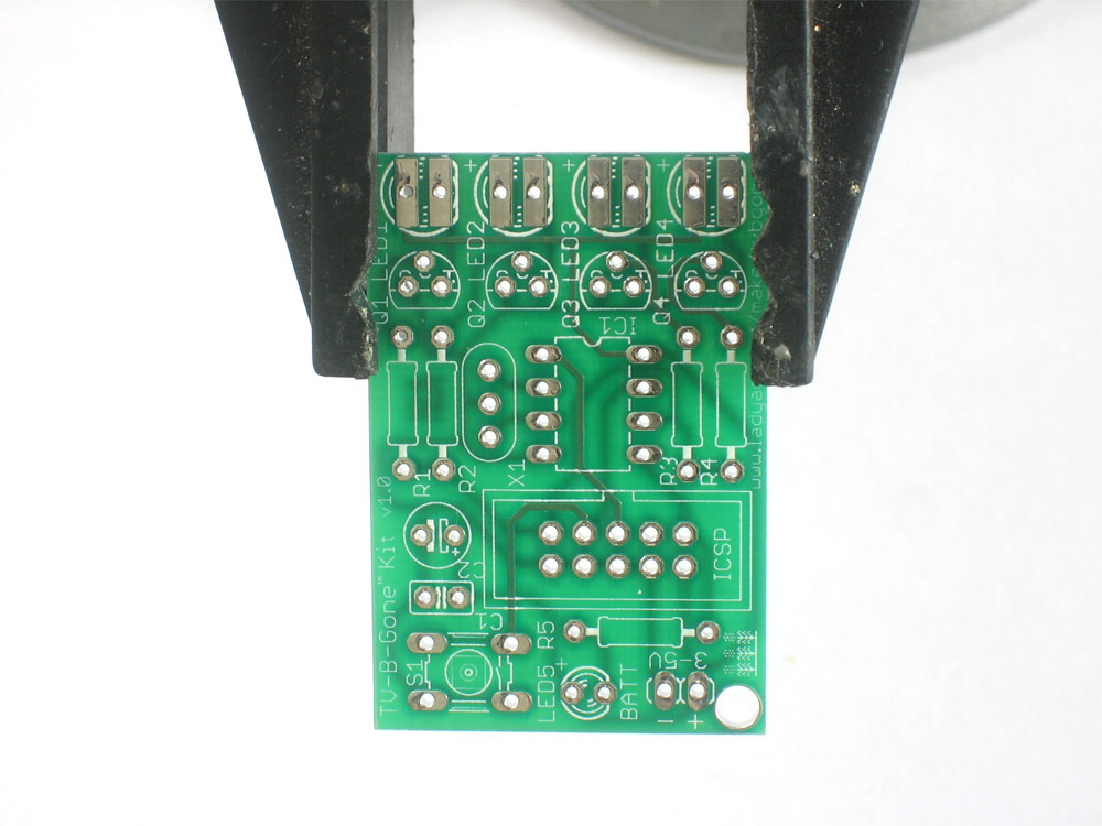 |
Put the printed circuit board into a vise or board holder, heat up your soldering iron and make sure you're ready to go! |
|
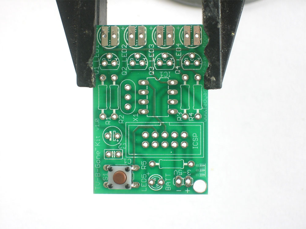
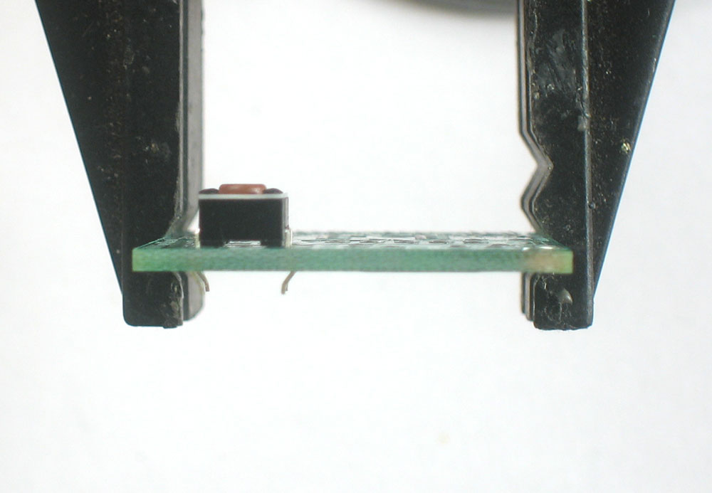
The first part we're going to assemble is the button. The button is a symmetric part so it can go in two ways. Line up the metal legs with the holes in the circuit board and snap it in. The button should sit flat against the circuit board. |
 |
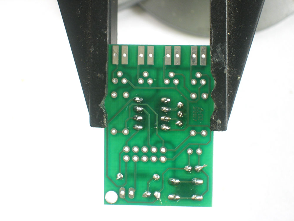
Using your soldering iron, heat up a leg of the button and the poke solder into it to make a nice solder joint. |
 |
Repeat for all four legs. The solder points should be clean and shiny. See the tutorials for soldering help if you can't get it right. |
|
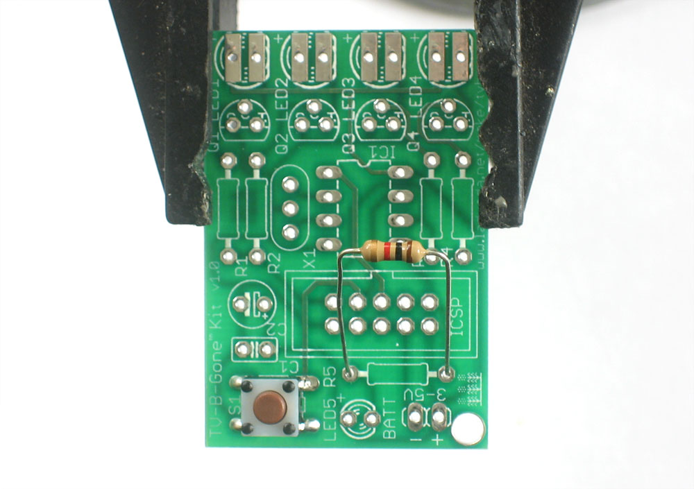
Next is the 1.0 kilo ohm resistor R5. This is the brown-black-red striped part. This resistor sets the brightness of the little indicator LED. Resistors are symmetric, so it can go in either way. Bend the legs so it looks like a staple and insert it into the R5 location as shown. Then bend the legs out a bit so that when you turn the PCB over the part doesn't fall out. |
|
solder each leg of the resistor |
|
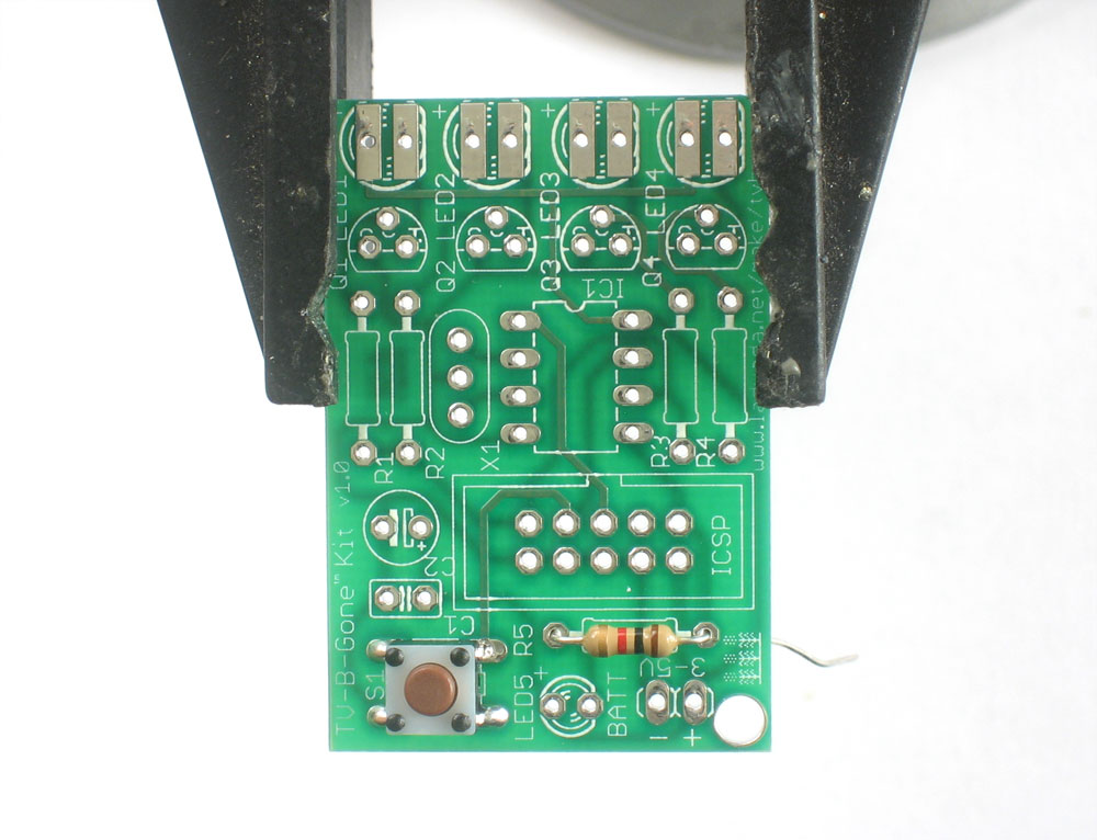
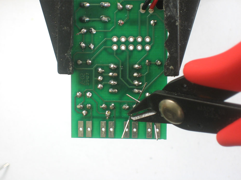
Use the diagonal cutters to clip off the resistor legs so that only the solder points remain. |
|
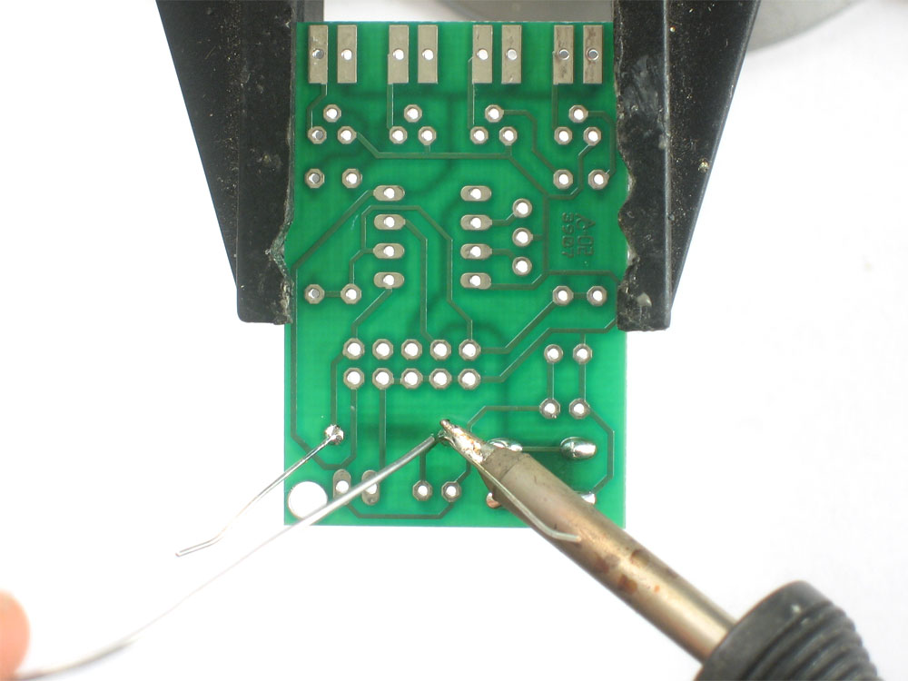
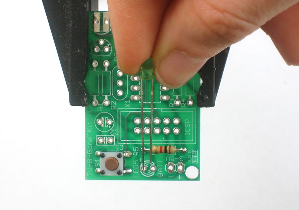
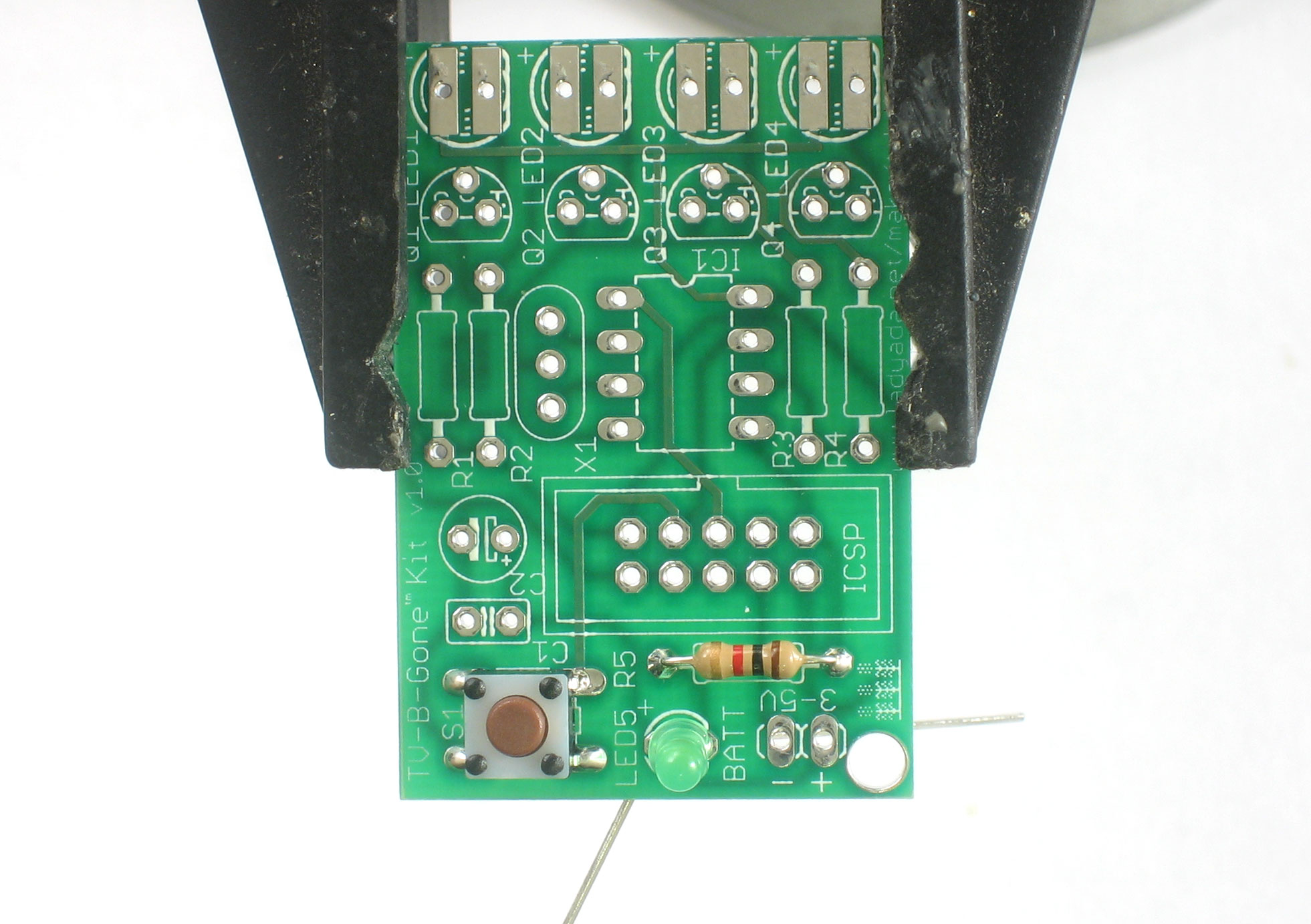
Now its time to place the small indicator LED LED5. LED's are not symmetric and must be placed correctly in order to work. You'll notice one leg of the LED is longer than the other. This is the positive leg. The positive leg goes into the hole with a + next to it. In the picture shown, its the left hole. Insert the LED into the correct location, and bend the leads out to keep it from falling out when you turn the PCB over. |
|
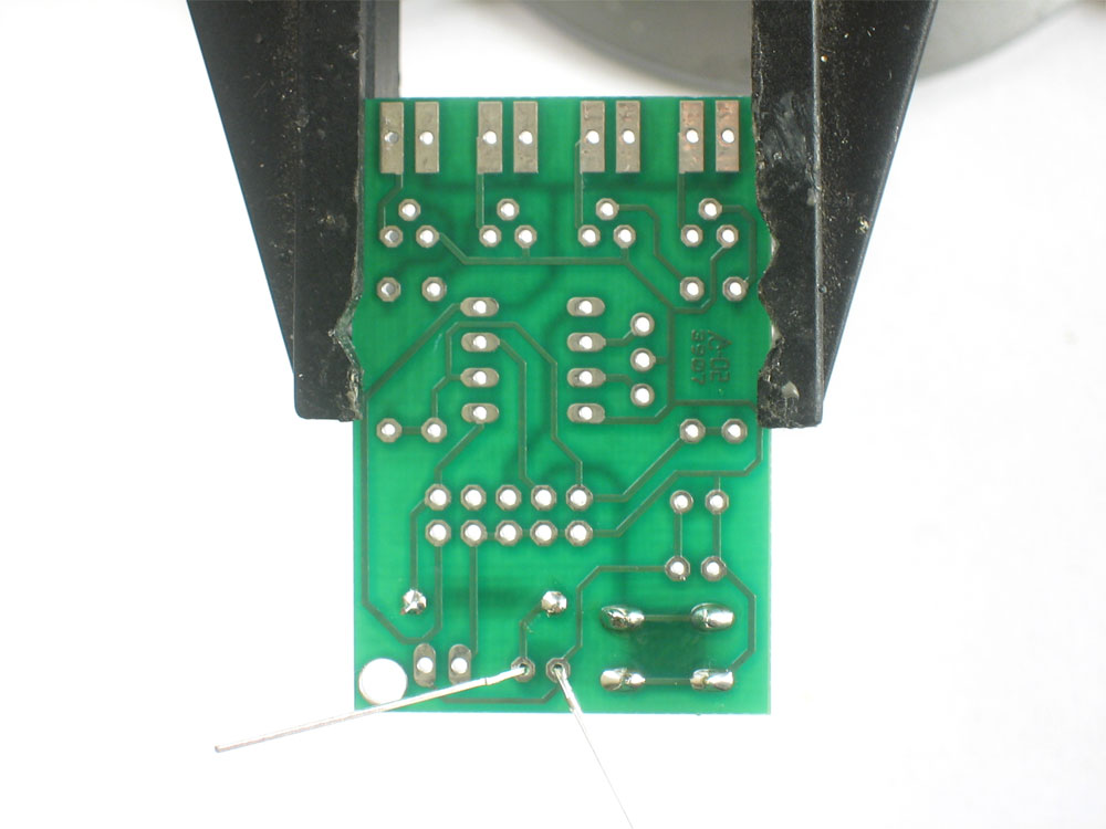
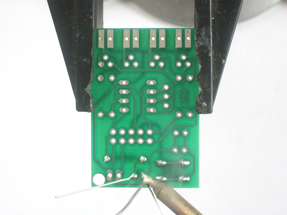
Turn the PCB over and solder both leads of the LED. |
|
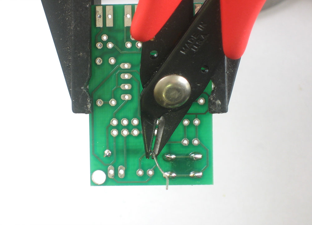
Clip both leads of the LED. |
 |
The next part is the ceramic capacitor C1. Ceramic capacitors are symmetric so it can go in either way. |
|
Solder and clip the ceramic capacitor part |
|
|
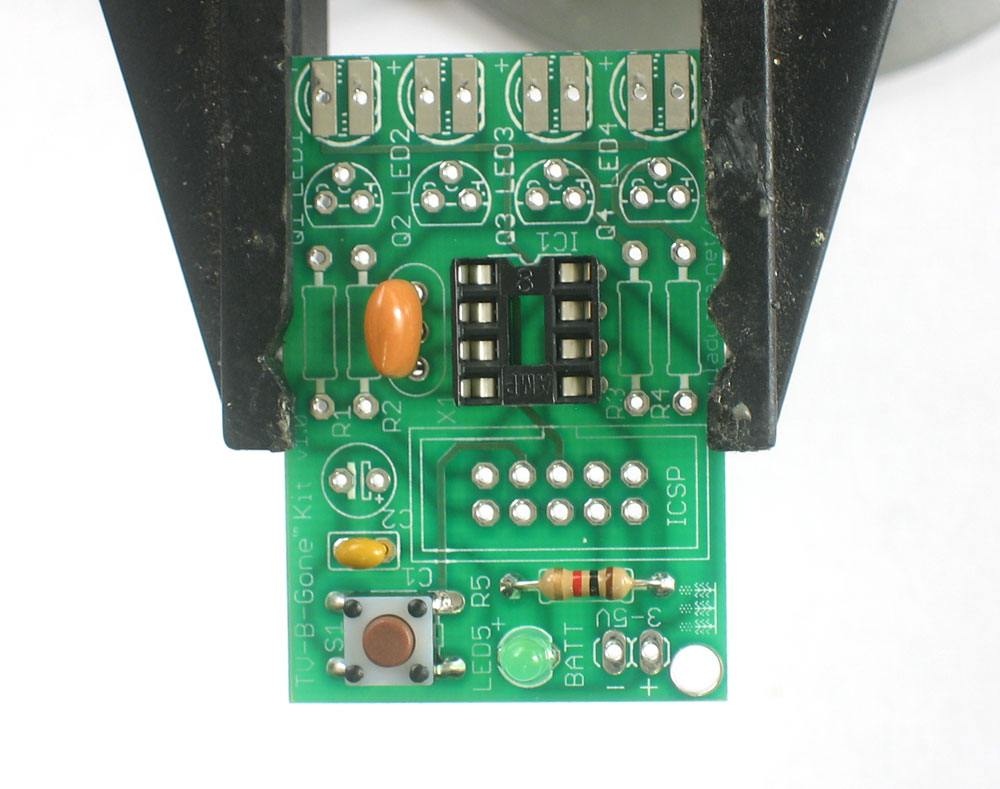
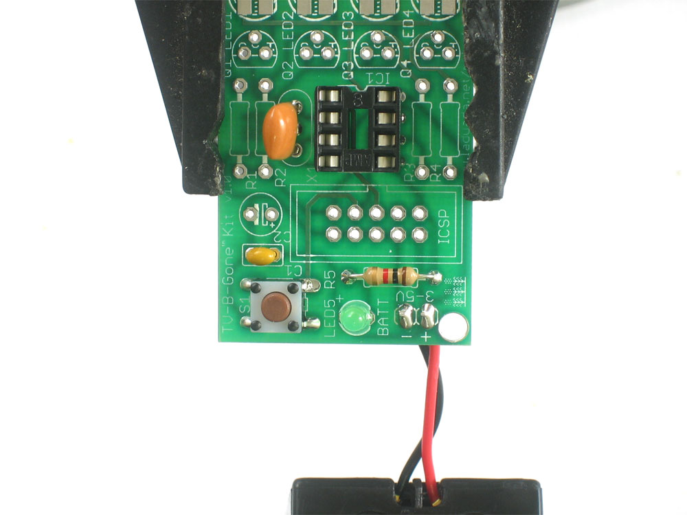
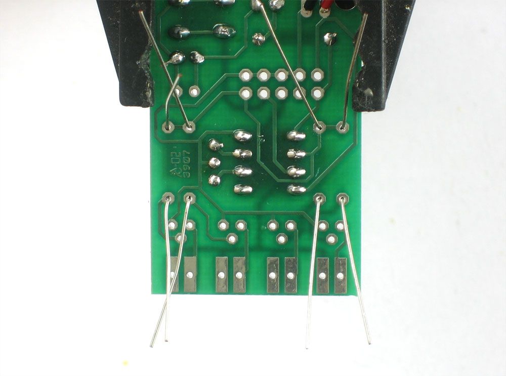
Next, place 2 components. The ceramic oscillator and the 8-pin socket. The oscillator has 3 pins and is symmeteric. The oscillator is the timeclock for the microcontroller, making sure that it is performing its functions at the correct speed. The socket is for protecting the chip and making it easy to insert and remove. The socket has a little notch in one end. That notch should match the one in the picture silkscreened onto the circuit board. This will help you place the microcontroller in properly later. |
|
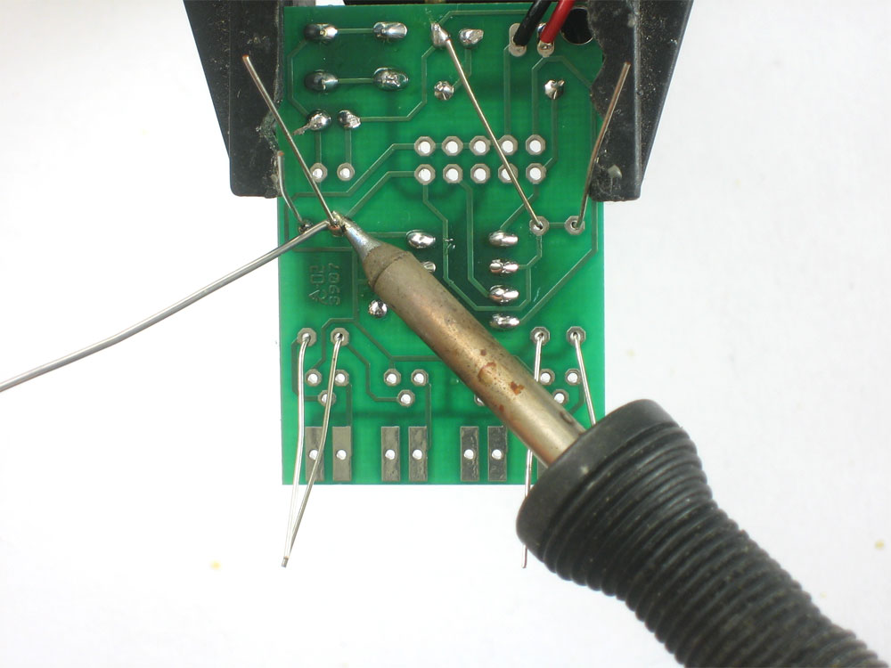
You may need to solder one pin of the socket while holding it it in with a finger (or tape) as the legs aren't long enough to be bent while in place. |
|
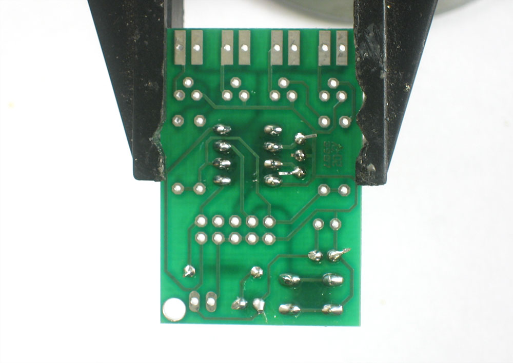
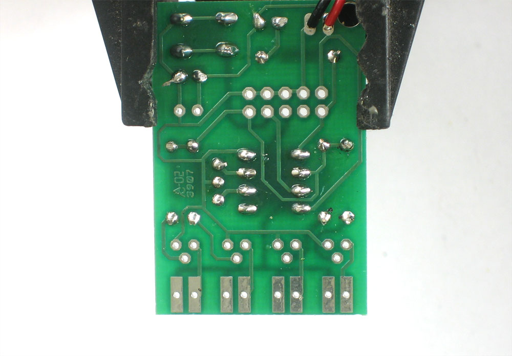
Solder the rest of the points then clip short the legs of the oscillator. |
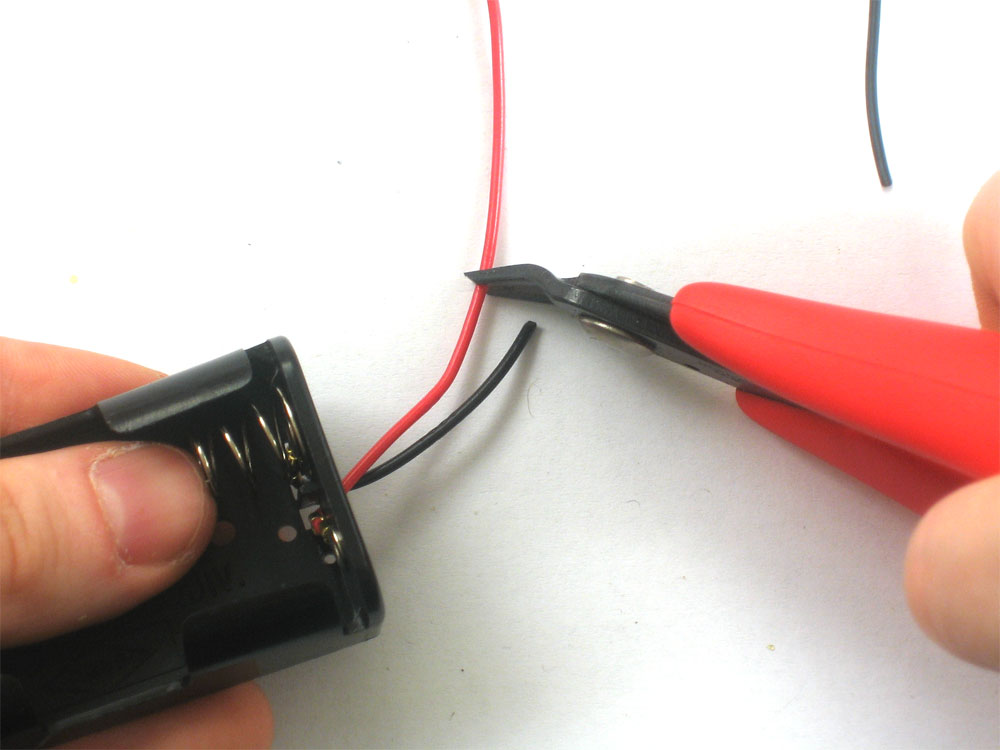 |
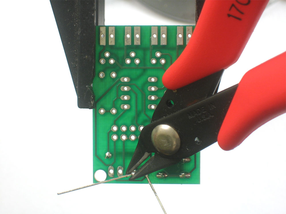
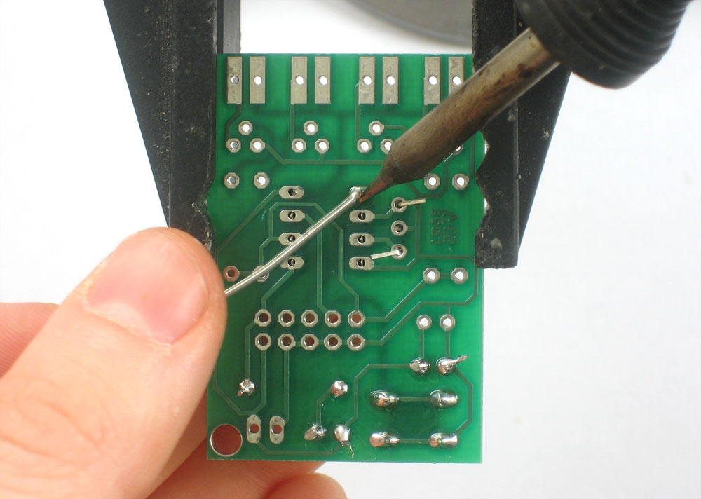
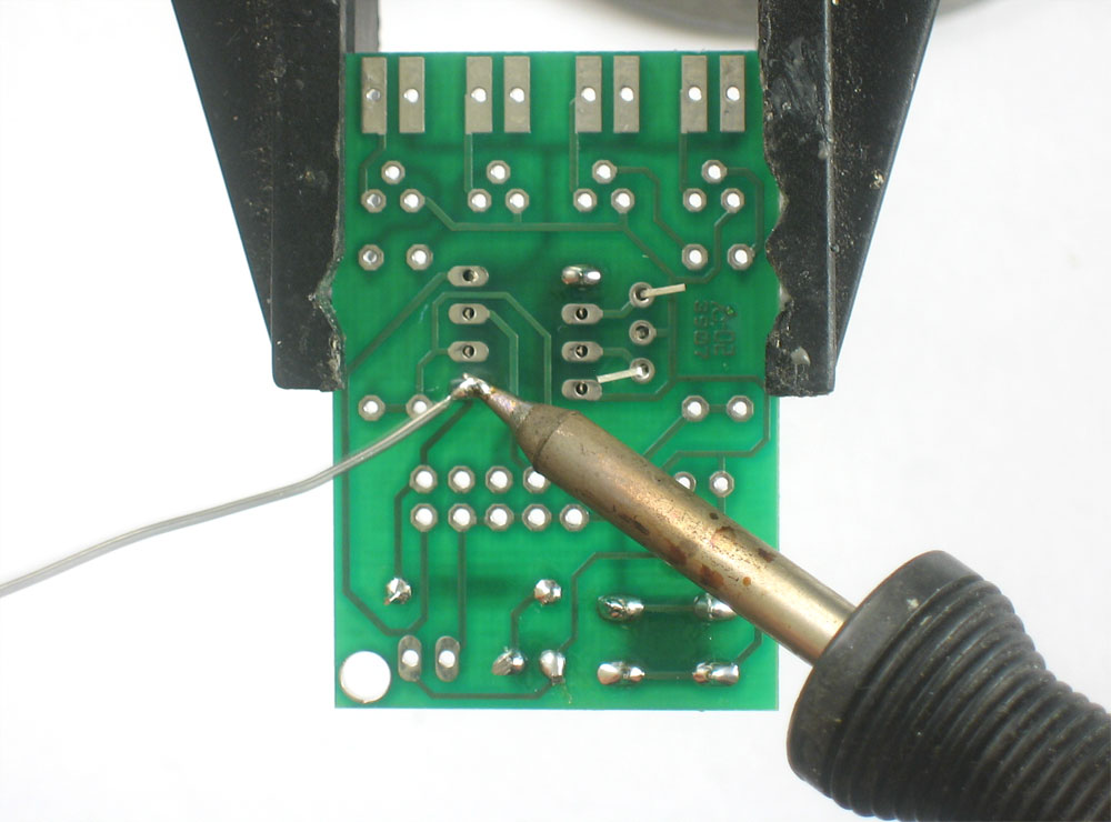
Next grab the battery holder and clip the leads short, to maybe 1.5" (4cm) long |
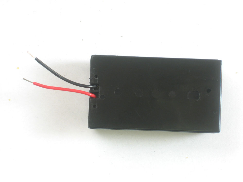 |
Strip the ends of the wire off so that there's a short section without insulation |
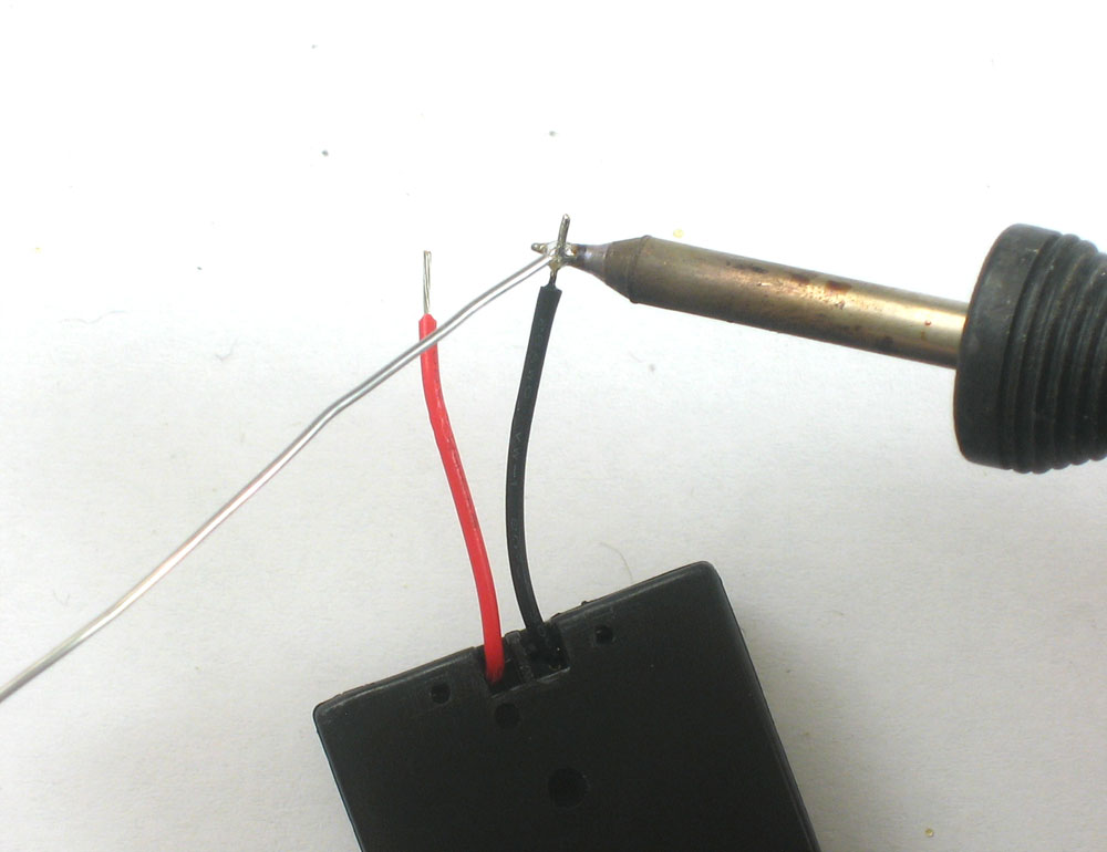 |
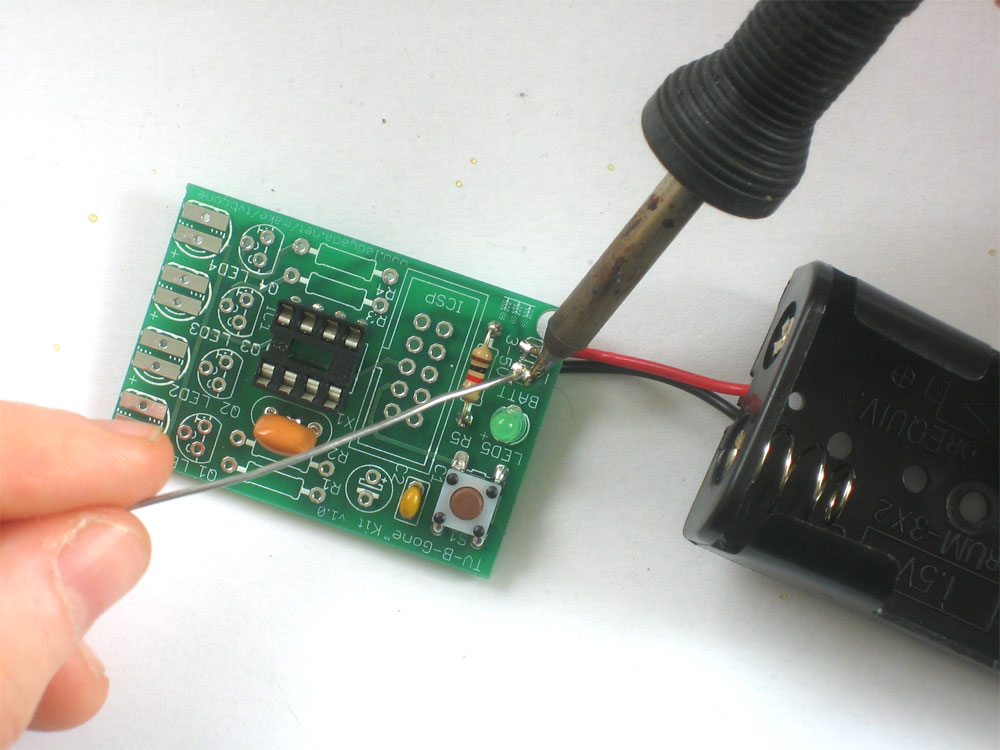
Use your soldering iron to 'tin' the wire, melting solder into it to keep the wire from fraying. |
|
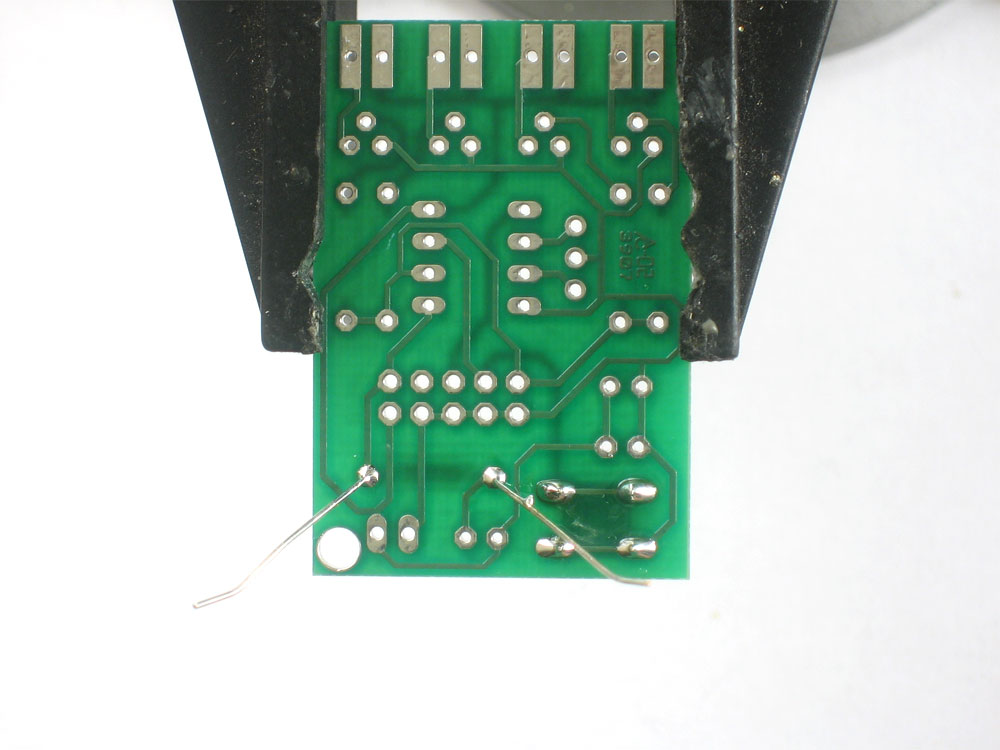
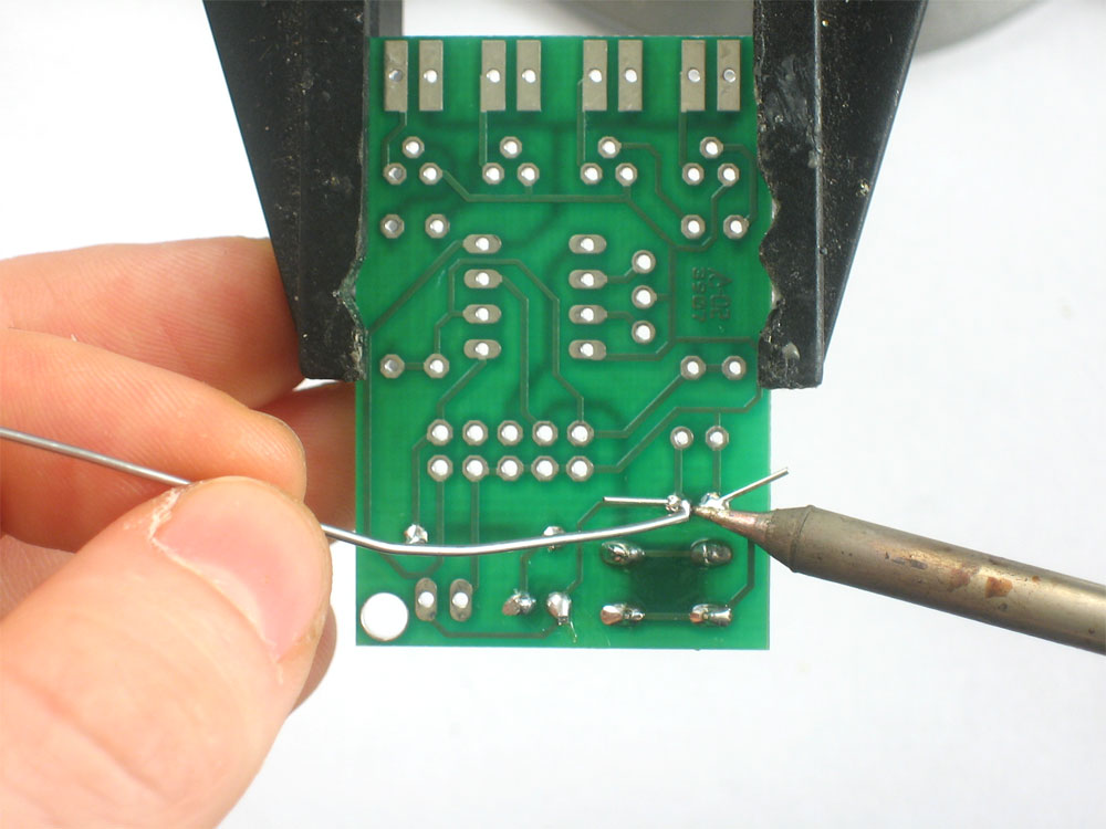
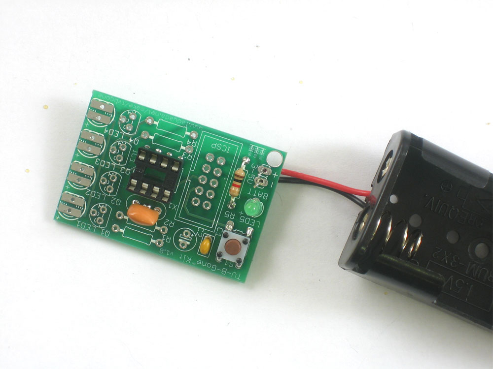
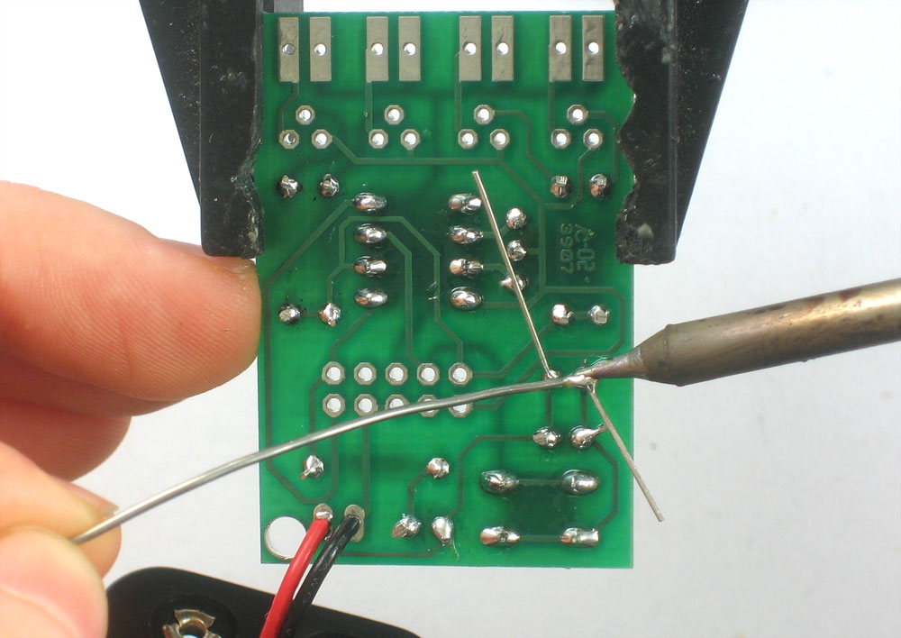
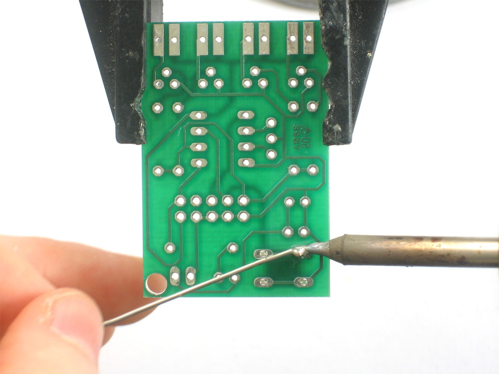
Insert the wires into the PCB so that the red wire goes to the + hole and the black wire goes to the - hole. Solder the wires, then clip them if they're too long. |
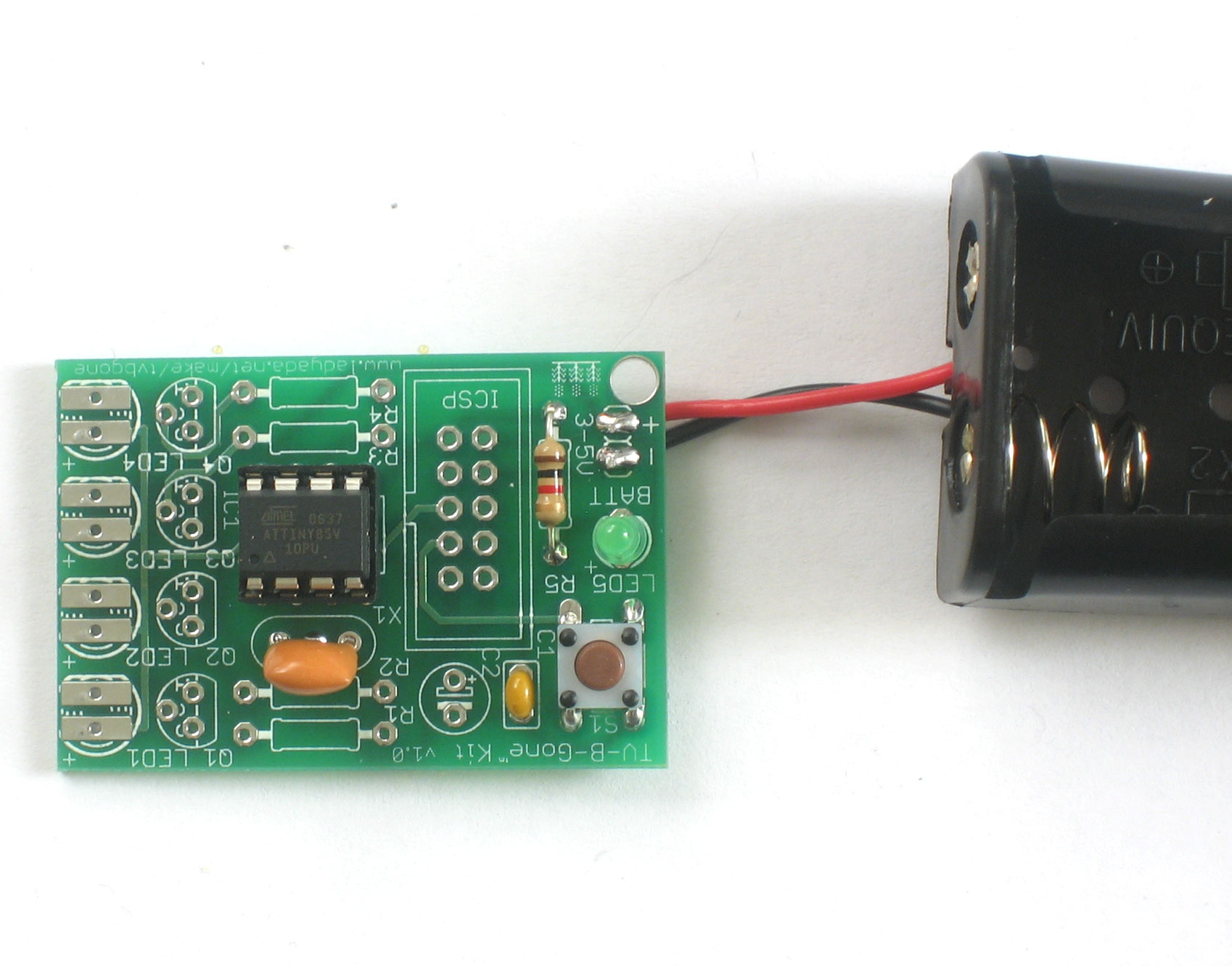 |
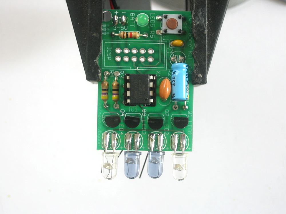
Carefully insert the microcontroller into the socket. Make sure that the little dot (and triangle) are at the end with the notch in the socket. In this photo, the dot is on the left. The microcontroller is the device that stores all the codes and turns the LEDs on and off according to a program. |
Test the kit now by putting two good AA batteries into the holder and pressing the button. The green indicator light should blink to show that the microcontroller is functioning properly. If you don't get a blinking light check the batteries, make sure the indicator LED is in correctly,and that the chip is in the right way. Once you've verified it's working, remove the batteries. |
|
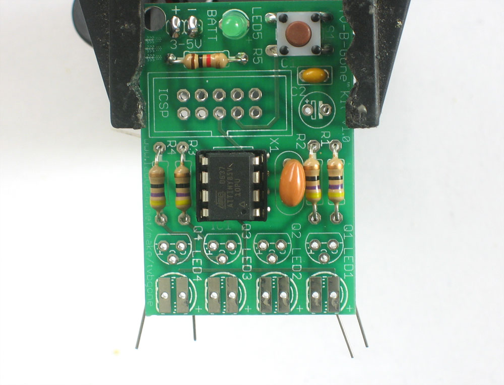 |
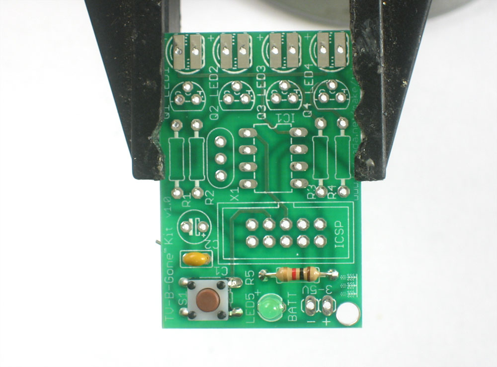
Next place the 4 47 ohm resistors, R1 R2 R3 R4. These are the parts that determine how bright the IR LEDs are. |
|
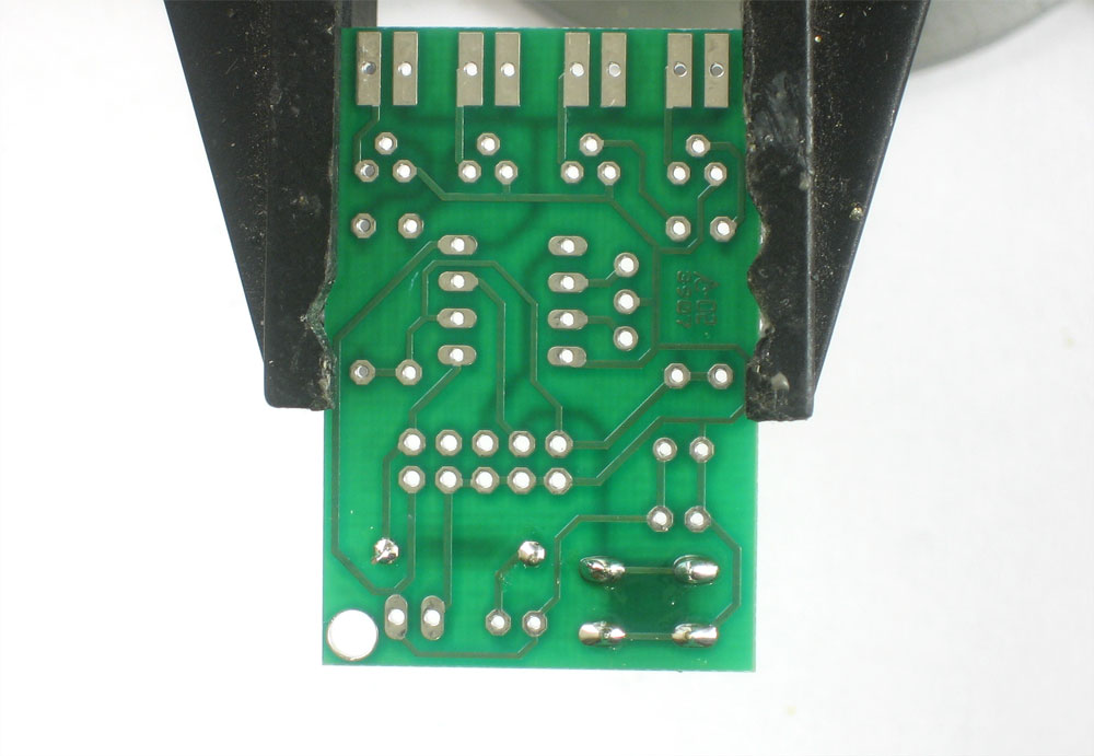
Solder and clip all 4 resistors. |
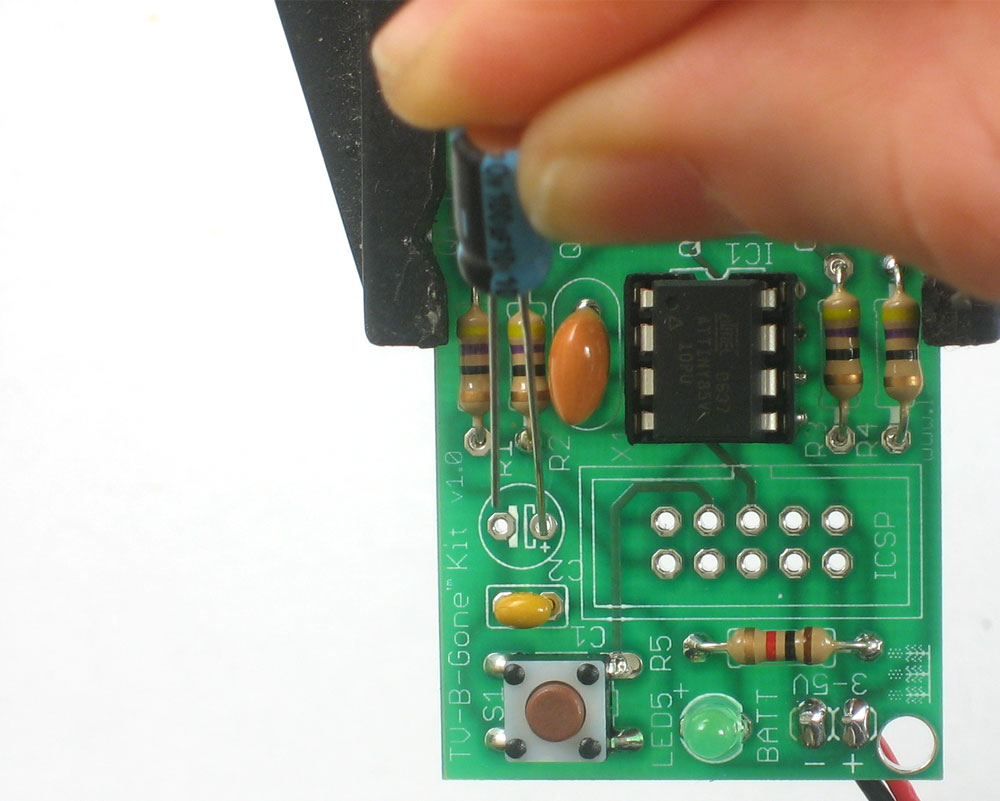 |
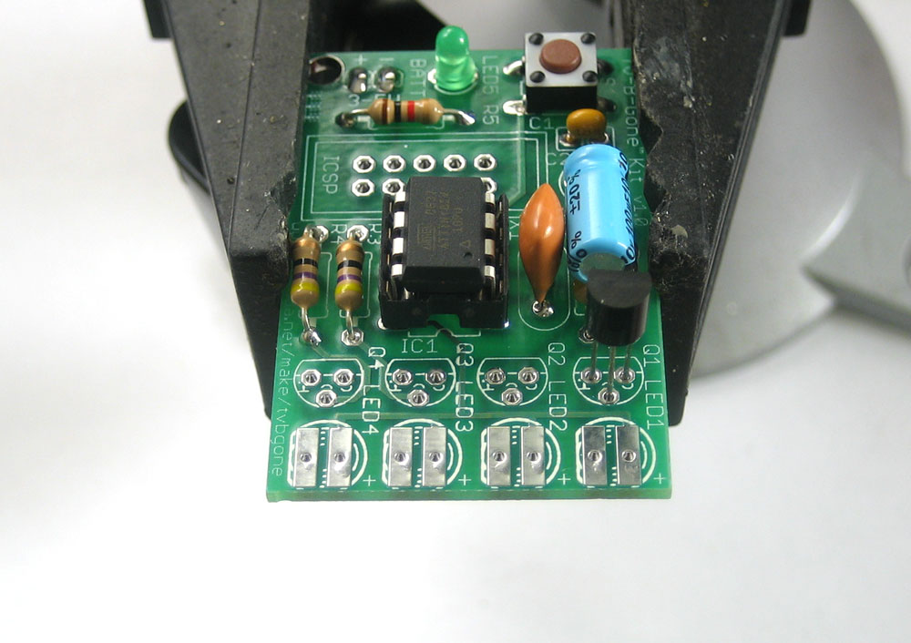
Next is the 100uF electrolytic capacitor. It is polarized so make sure it goes in the right way. The long lead is positive, and goes into the hole marked with a +, on the right in this photo |
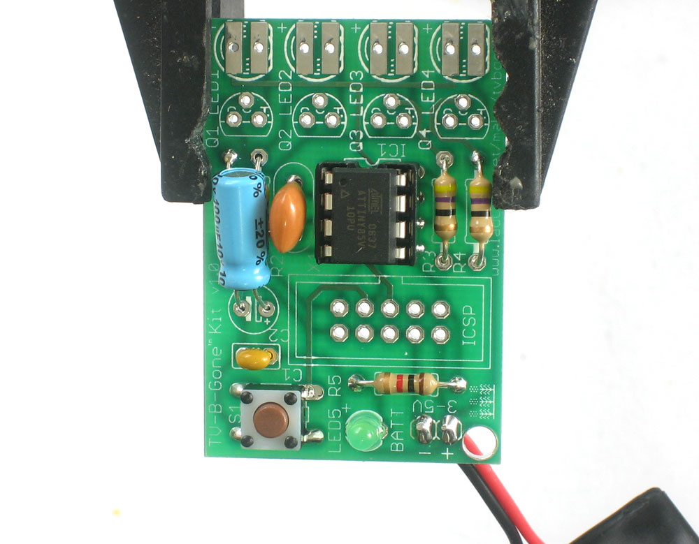 |
Bend the capacitor so it lies over the resistors, this will make it stick out less. |
|
|
|
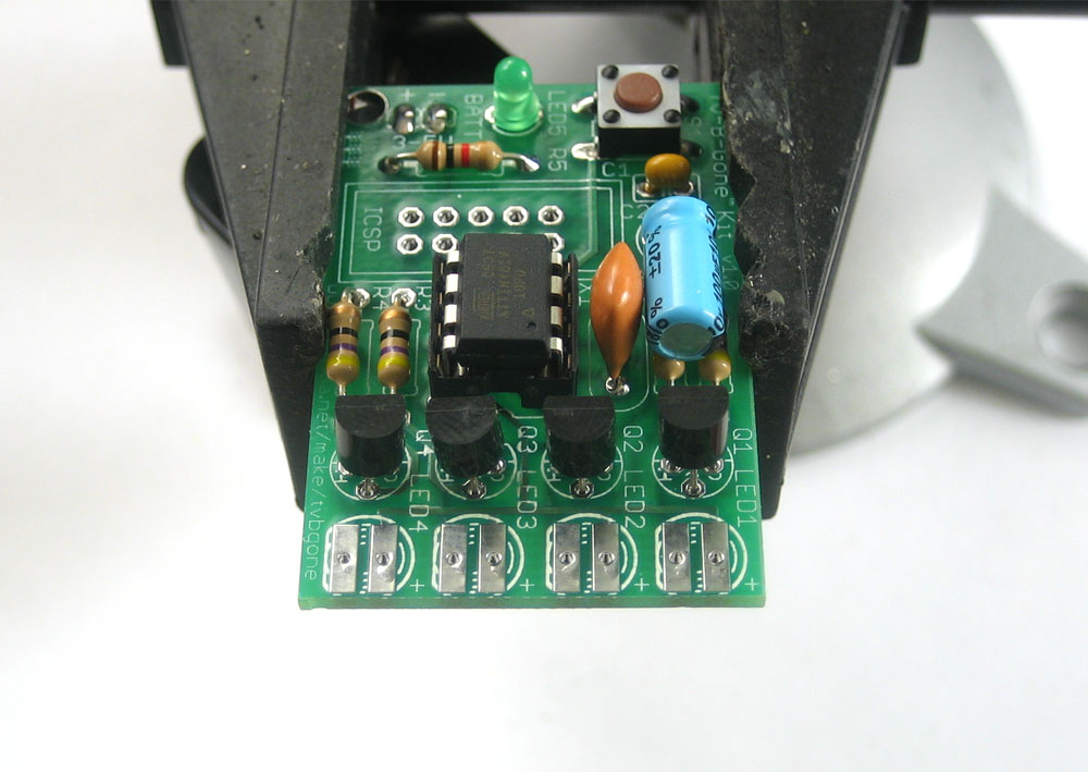
Next are the four transistors Q1 Q2 Q3 and Q4. These are the devices that turn on and off the high power IR LEDs. The microcontroller doesn't have the capability to provide a lot of power directly to the LEDs so these transistors assist it. Transistors have three pins. bend the middle pin back a little and insert it so that the rounded and flattened sides match up with the picture silkscreened onto the circuit board, as shown. The transistor won't be able to sit flat against the circuit board, so just make it poke up a few millimeters. Insert all 4 transistors. |
|
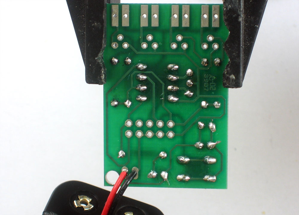
Turn the PCB over and solder in all the transistors. Then clip the wires. |
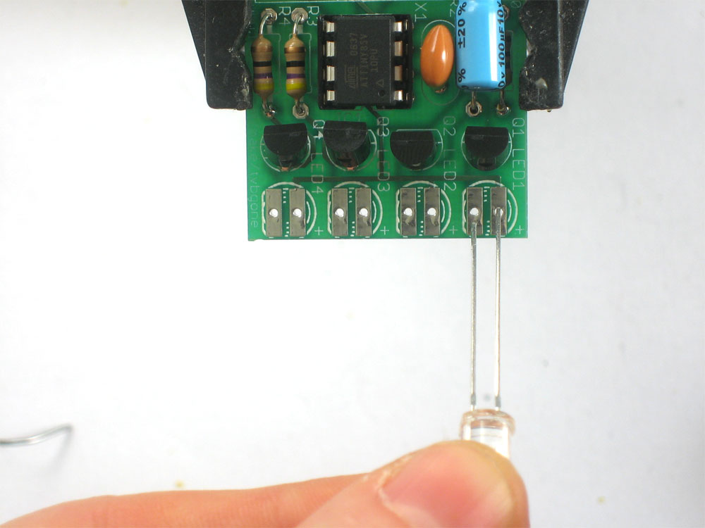 |
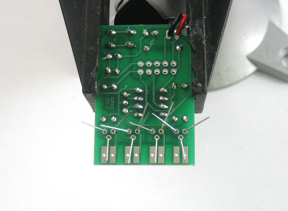
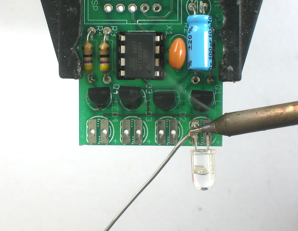
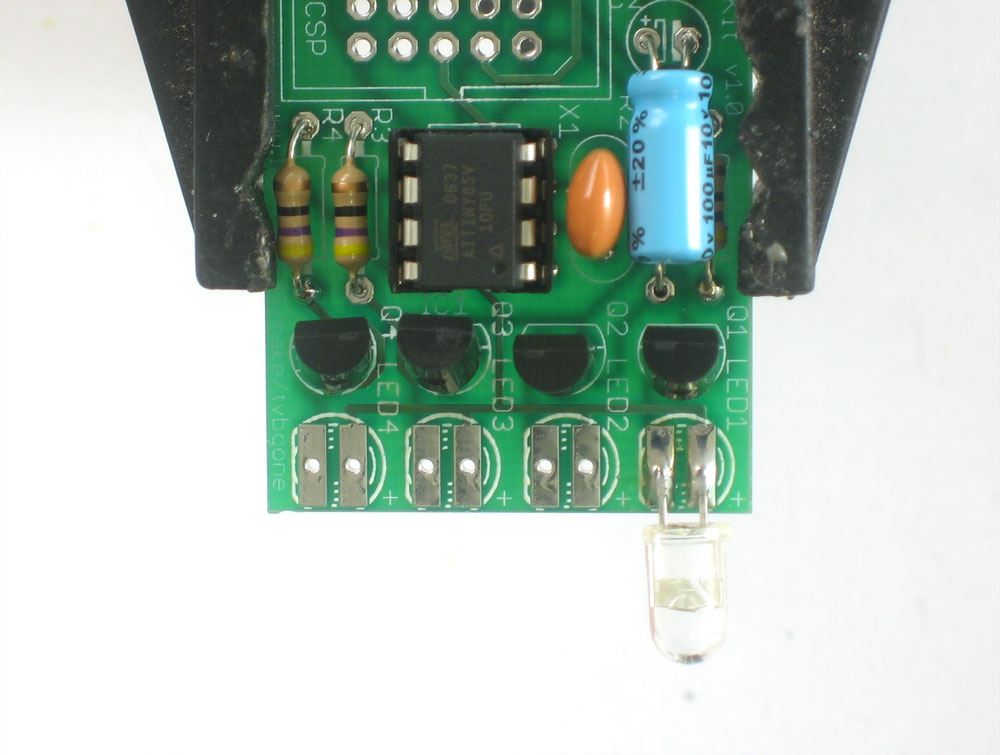
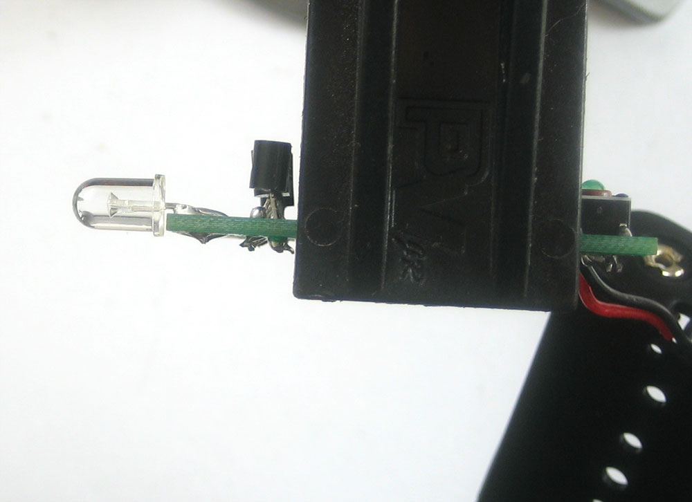
Next is the IR LEDs. Start with LED1, a clear IR led. Like the small indicator LED, it has polarity. Make sure the longer, positive lead is on the right, as shown. |
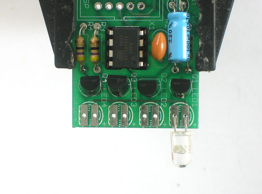 |
Bend the LED over 90 degrees so it sticks out over the edge of the circuit board |
|
Now solder it to the top of the circuit board |
|
|
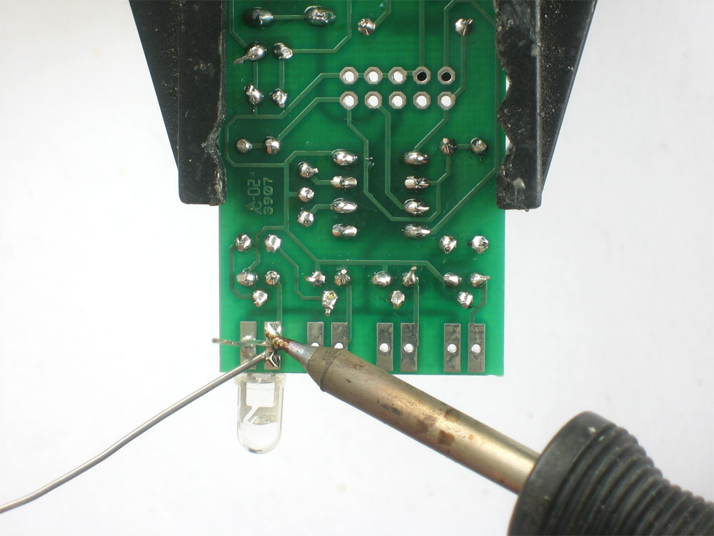
Flip over the PCB and solder it to the bottom (if necessary) Then clip the leads |
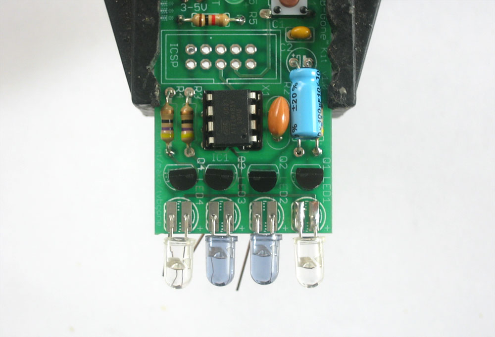 |
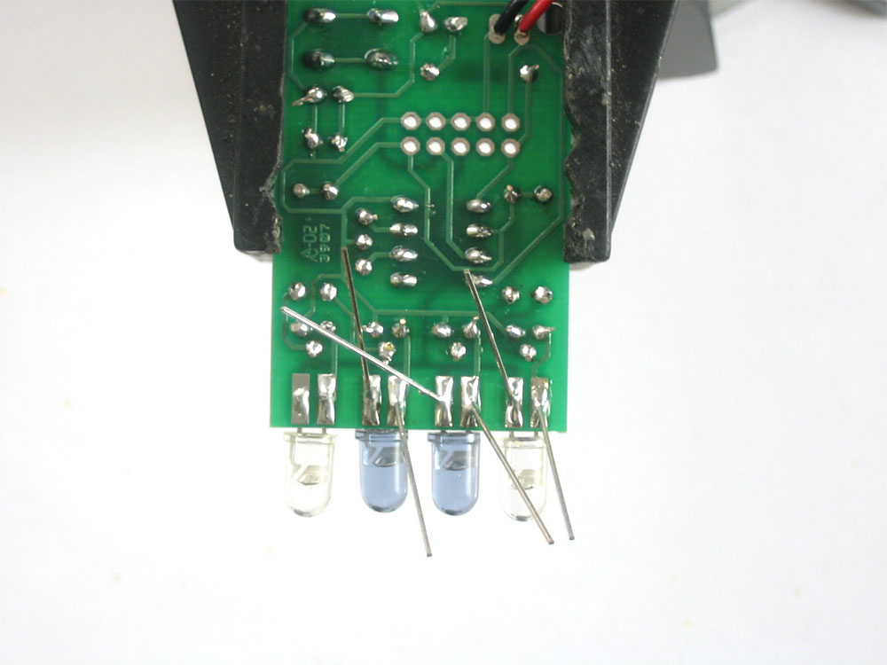
Place the remaining LEDs. The blue tinted ones should go in the center. Make sure they are in the correct orientation! |
|
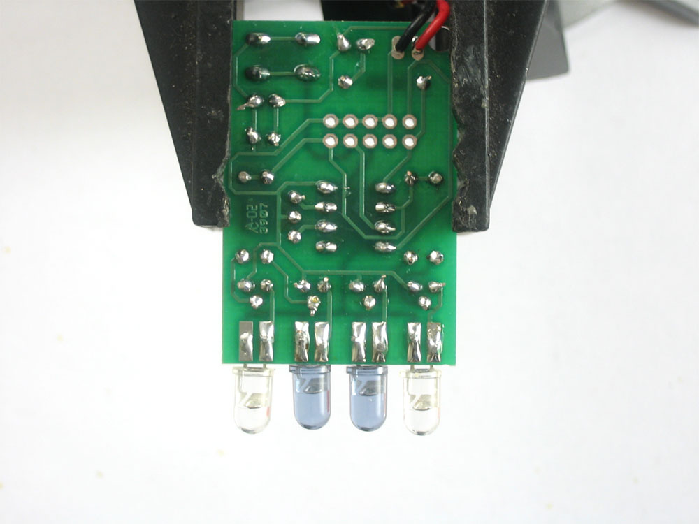
Solder the LEDs in and clip the long leads. |
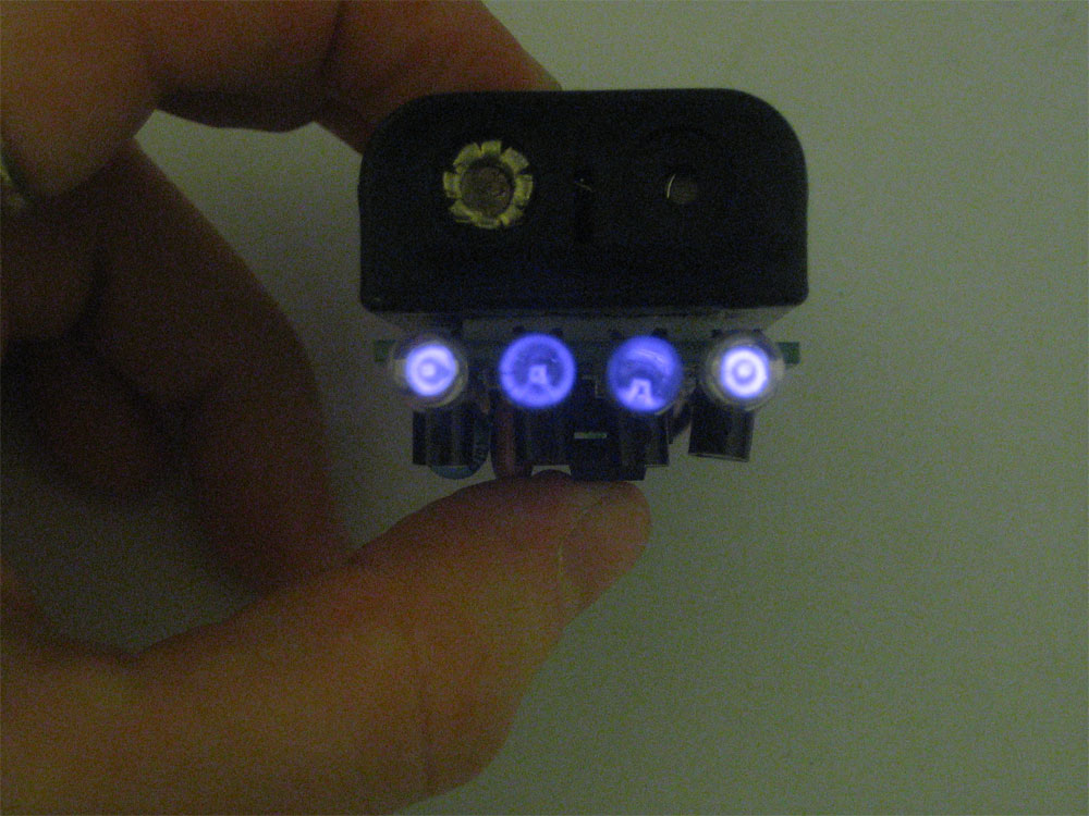 |
You're done soldering! Now you may want to perform some tests to make sure its working. Visit the Testing page for more info. |
|
Place the doublesided foam sticky on the circuit board. Remove the other side and press the battery holder on |
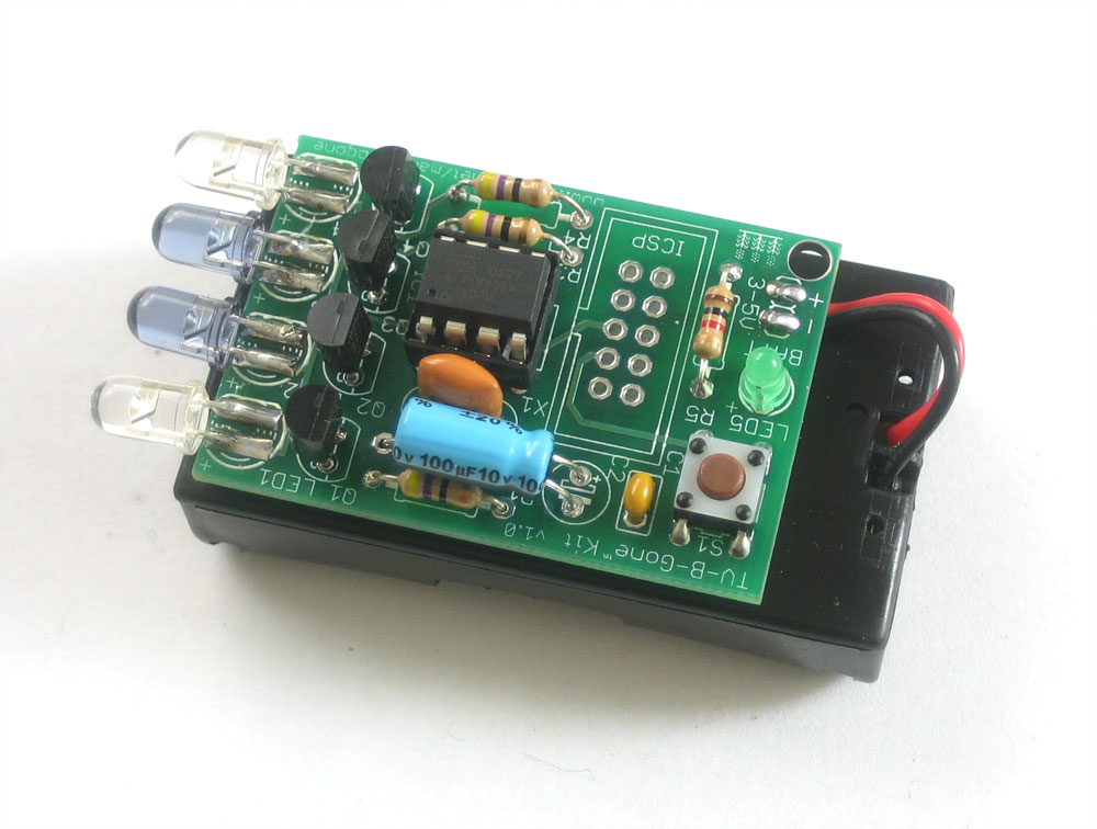 |
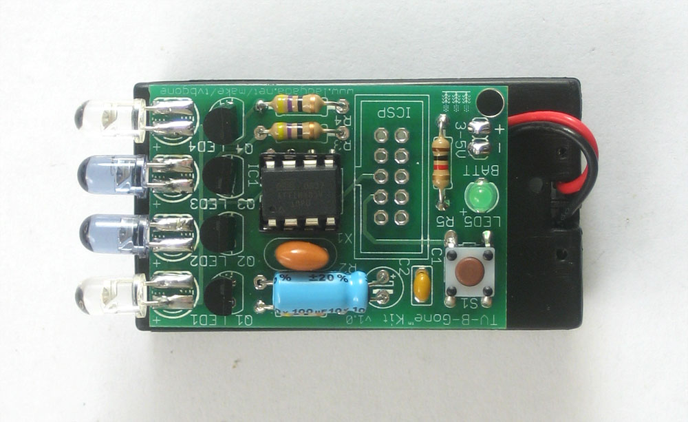
Congrats, you're done! |