OK so that was fun and all...you learned how to use 3 colors and mix them to make 3 more colors. Clearly its a start, but really you know that there's way more colors you can make with the primary red/green/blue. Hell, look closely at a TV/CRT screen and you'll see that all the pixels are also RGB and there are at least a thousand colors a TV can display. Thats because we're only mixing 100% red and 100% blue to make pure magnenta. What we really want to do is mix different proportions of color, as described by the CIE colorchart.
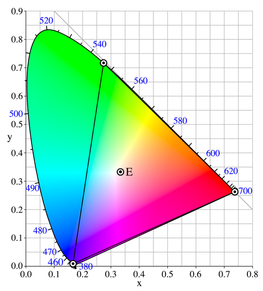
The CIE chart is a triangularish wedge which shows all the colors the eye can see, where the top left corner is pure green, the bottom right is pure red and the bottom left is pure blue. The numbers on the perimeter are corresponding wavelength (in nanometers) The inscribed triangle is a demonstration of actual color generated. For example, lets say our RGB LED can generate the following pure wavelengths: 700nm (red), 545nm (green) and 400nm (blue). That would correspond to the points plotted on the CIE chart and so we can make any of the colors inside the triangle, but none outside of it. Of course, your CRT/LCD monitor also has a triangle of possible colors, which explains why the sections of color outside the triangle don't really look different than the color inside.
We don't actually know the wavelengths of the LEDs in this LED because we don't have a datasheet, but it's probably close to the above numbers.
00029 int main(void) {
00030   // initialize the direction of the B port to be outputs
00031   // on the 3 pins that have LEDs connected
00032   set_output(DDRB, RED);
00033   set_output(DDRB, GREEN);
00034   set_output(DDRB, BLUE);
00035
00036   // start with all the LEDs off
00037   output_low(PORTB, RED);
00038   output_low(PORTB, GREEN);
00039   output_low(PORTB, BLUE);
00040
00041   // simple pulse width modulation
00042   while (1) {
00043     // red led is 'off' for 3x longer than it is on...a PWM duty cycle of 25%
00044     output_high(PORTB, RED);
00045     delay_ms(1);
00046     output_low(PORTB, RED);
00047     delay_ms(3);
00048   }
00049 }
OK so this is sort of like ledblink.c except now we're blinking the LED much faster and we're not blinking it evenly: the led is on for 1ms and off for 3. In other words, the positive pulse width is 25% (1ms out of 4ms) and the negative pulse width is 75% (3ms out of 4ms). The period of the pulse is 4ms, thats the total time for one cycle of on/off.
Compile and upload this code.- Try to create PWM waveforms of 25%, 50%, 75% for green and blue LEDs also
- Adapt the code so that, with a 4ms PWM period, you have red on for 25%, green on for 50% and blue on for 75%
- Adjust the period to be 10ms, 20ms, 50ms, etc. At what point does the pulsing become obvious?
After each exercise, (gently) shake the board, to examine the PWM 'trails'
We've observed that we can make the red LED appear 'dimmer' by PWMing it. For our next trick, we will make the LED 'pulse,' a common trick used on consumer electronics. To do this, we will ramp up the PWM from 0% to 100% over the course of a second or so.
00030 int main(void) {
00031   int8_t i;
00032
00033   // initialize the direction of the B port to be outputs
00034   // on the 3 pins that have LEDs connected
00035   set_output(DDRB, RED);
00036   set_output(DDRB, GREEN);
00037   set_output(DDRB, BLUE);
00038
00039   // start with all the LEDs off
00040   output_low(PORTB, RED);
00041   output_low(PORTB, GREEN);
00042   output_low(PORTB, BLUE);
00043
00044   // simple pulse width modulation
00045   while (1) {
00046     // fade
00047     for (i=0; i <= 25; i++) {
00048       output_high(PORTB, RED);
00049       delay_ms(25-i);
00050       output_low(PORTB, RED);
00051       delay_ms(i);
00052     }
00053     // brighten
00054     for (i=25; i >= 0; i--) {
00055       output_high(PORTB, RED);
00056       delay_ms(25-i);
00057       output_low(PORTB, RED);
00058       delay_ms(i);
00059     }
00060   }
00061 }
Note that, here, we have two subloops in the main loop. The first one starts with the LED all the way on, and then reduces the brightness a 1/25th at a time, until the led is off. Then it ramps up again, turning the LED on more and more until its on all the way, then it continues.
- Take the PWM fading code and modify it so that it starts with red on all the way on and blue all the way off and then fades to red being all the way off and blue all the way on.