These are instructions for v1.2 only! For older instructions, see here
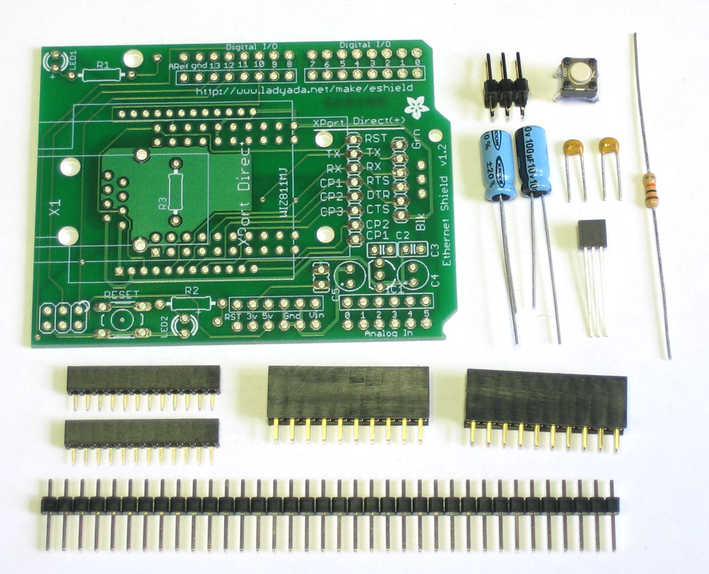 |
First off, check that you have all the parts. They're listed on the bill of materials page. |
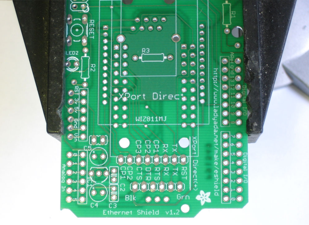 |
Next, get ready by placing the PCB in a vise so that you can easily place and solder the parts in! Check also that you have all the tools you need, & warm up your soldering iron to 650-700degF |
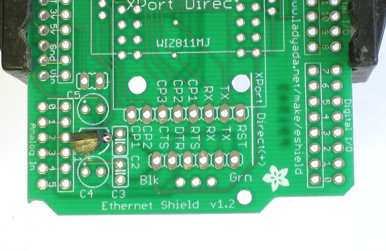 |
The first section is the 3.3v regulator, which is what we use to power the XPort/WIZnet modules. While latest Arduinos do have a 3V line, its not nearly powerful enough to run the XPort. Insert the MCP1700 regulator. Make sure its placed properly, such that the round and flat halves are aligned as indicated on the PCB silkscreen. Because the legs of the IC have to bend, it wont sit right up against the PCB, this is OK. |
|
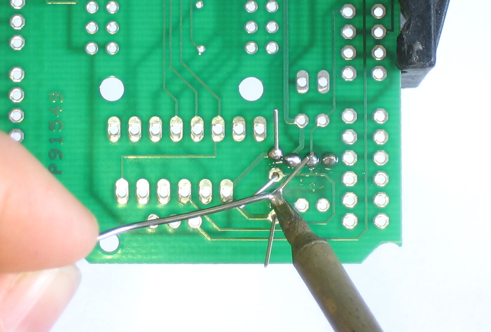
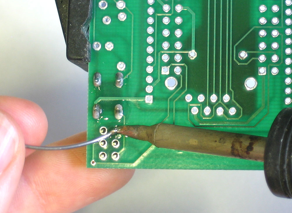
Next, with your soldering iron, solder each of the thee legs of the IC. Place the tip of the iron against both the pad (ring) and lead (leg) and after a few counts, touch the solder in, to make a nice joint. Repeat for all three joints. |
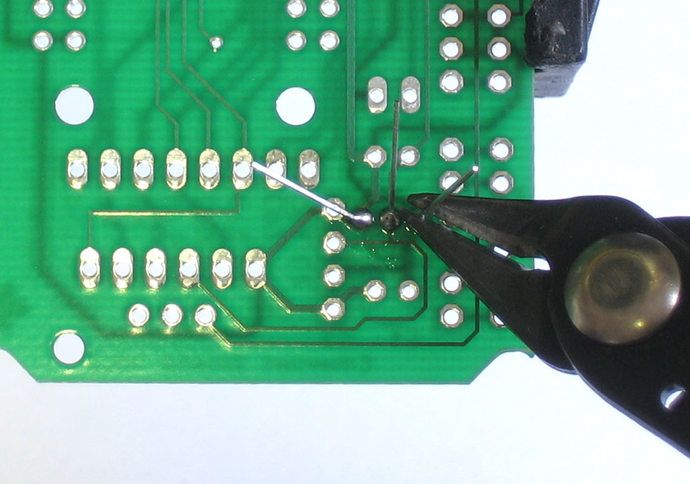 |
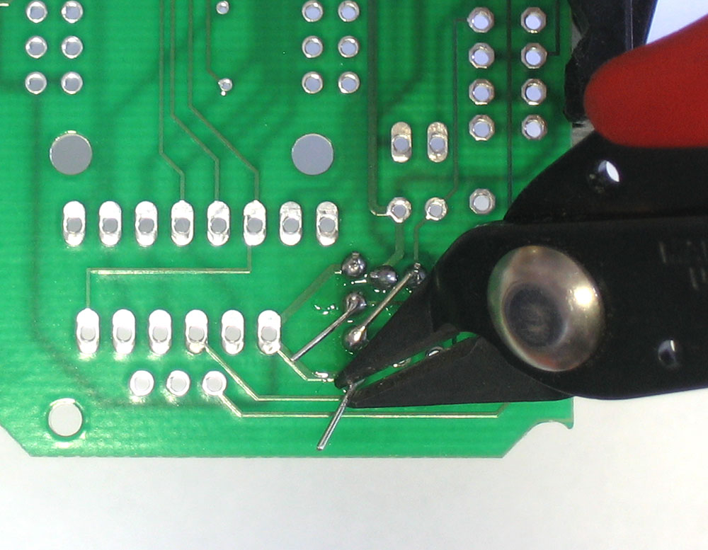
Next, clip the excess leads using the diagonal cutters. Clip right above the top of the solder joint. |
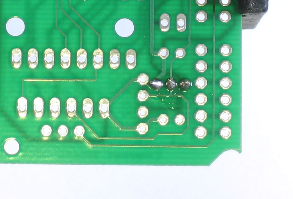 |
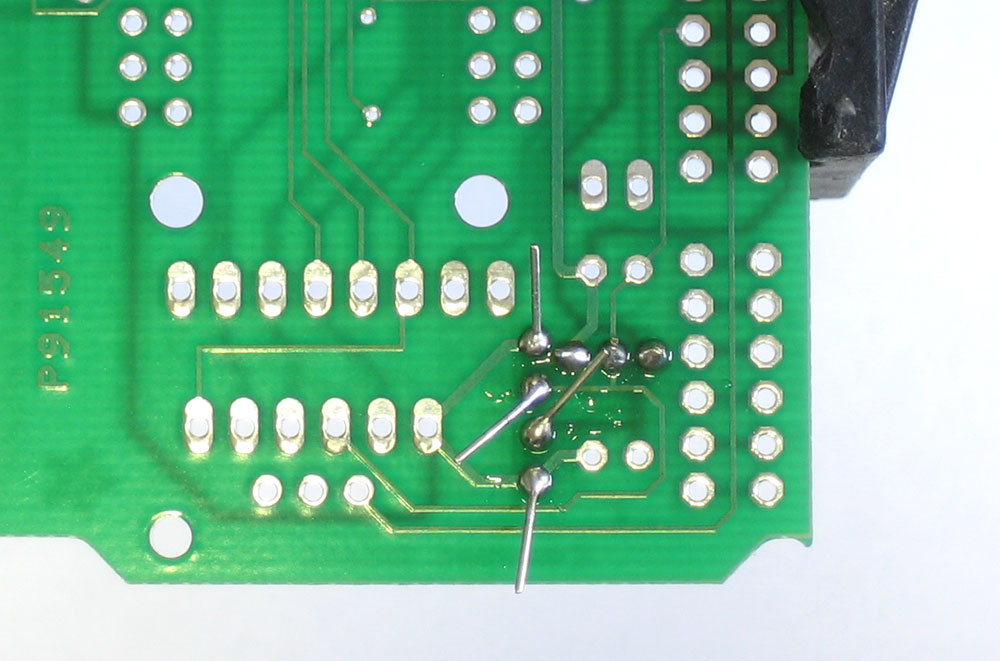
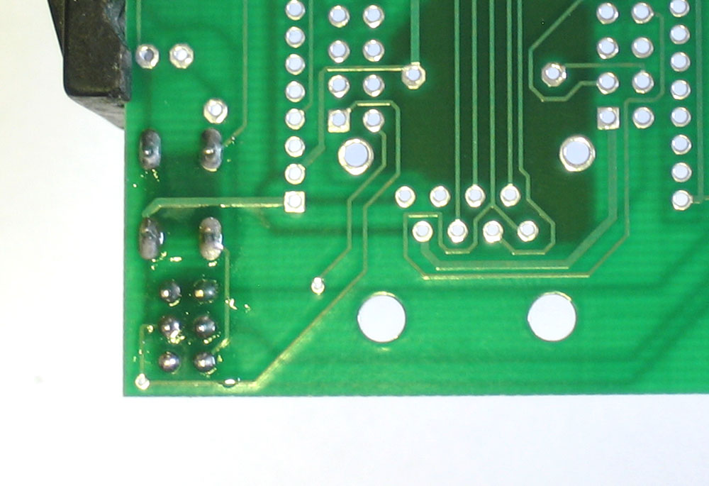
When you are done, it should look like this. If you have some sticky stuff on the solder joints, thats OK, thats the rosin inside the solder that protects the joints from oxidation. It isnt necessary to clean it off. |
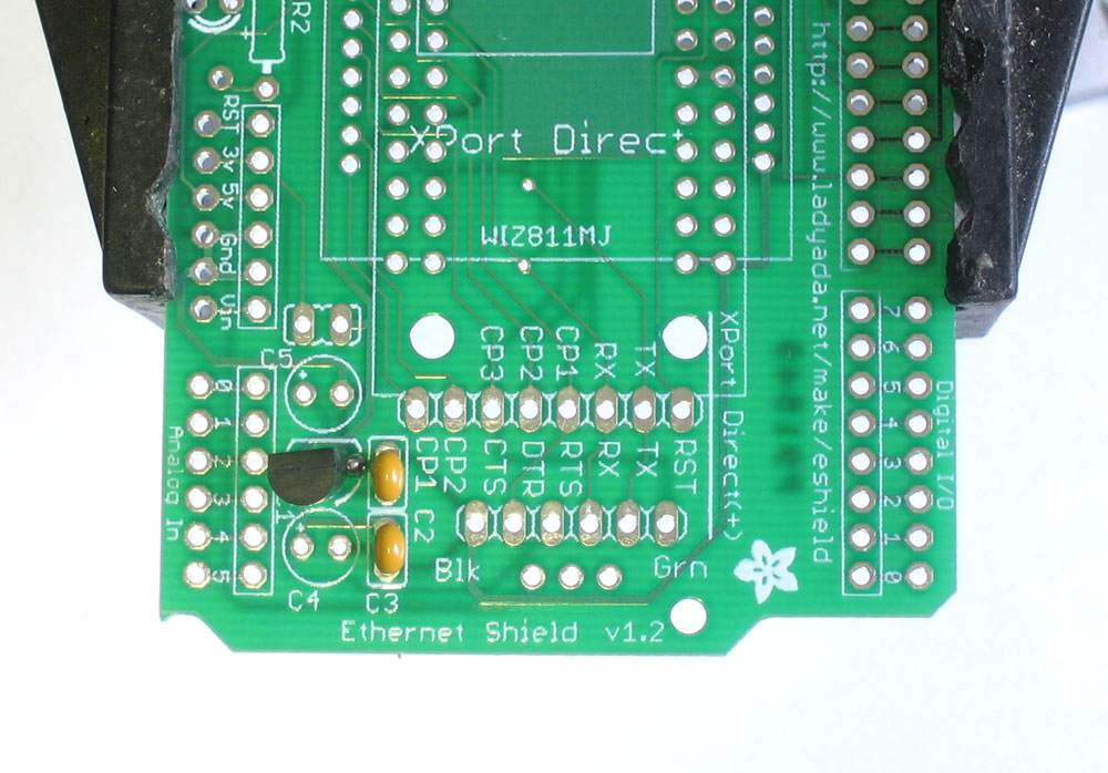 |
The next step is the two ceramic bypass capacitors for the input and output of the voltage regulator. They are used to get rid of high frequency noise on the power supply. Ceramic capacitors are non-polar. That means you can place them "either way" |
|
Turn over the board and solder in the 2 capacitors. |
|
Then clip the leads down. |
|
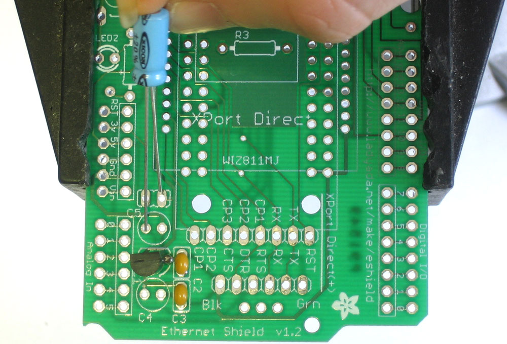
Next are the 2 electrolytic capacitors, which provide low-frequency filtering for the 3.3v power supply input and output. Electrolytic caps are polarized, and thus must be placed correctly or they will not work (and possibly 'explode'!) To place correctly, first identify which hole is for the positive lead. On the silkscreen you will see a small + next to this hole. Next, make sure the capacitors are inserted so that the long lead is placed in this hole. Compare with the images to the left. |
|
Turn the board over. Solder and clip the capacitors. |
|
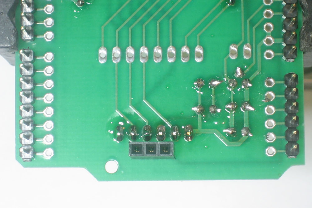
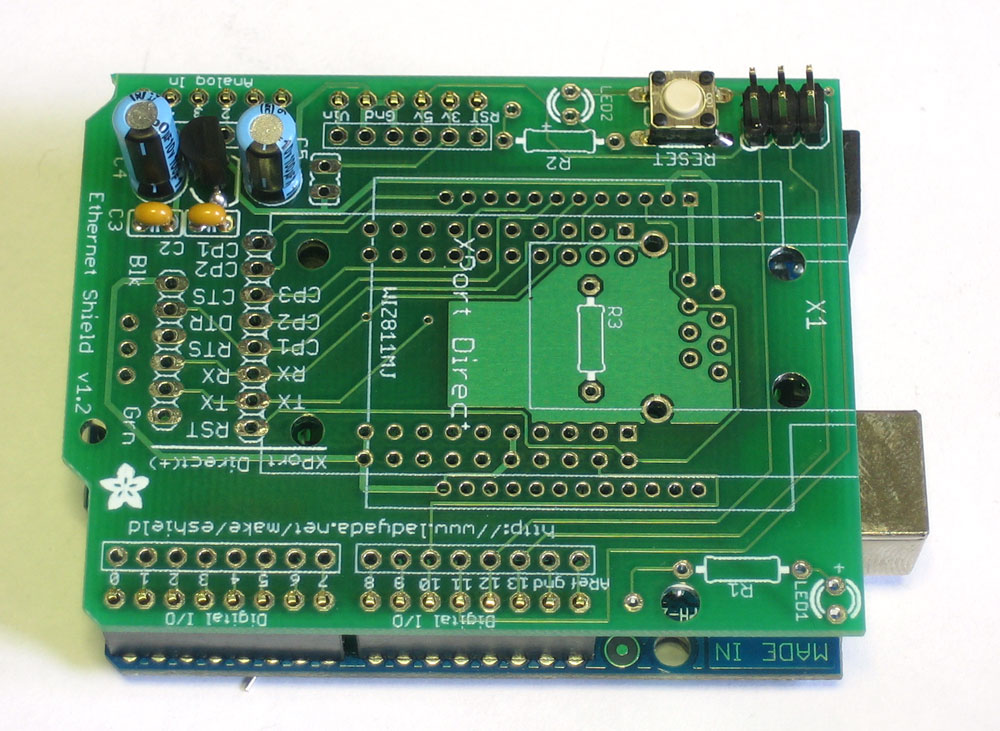
Next, place the tactile switch and 6-pin ICSP header. The switch will let you reset the Arduino even with the shield on, very useful when debugging a project! The 6-pin header will let you use a programmer if you don't want to use the Arduino software/bootloader. The switch should snap in, make sure it lies flat! |
|
Turn over the circuit board and solder in the switch and header. You wont need to clip the leads, they're quite short already |
|
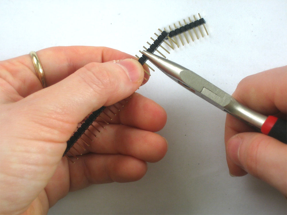
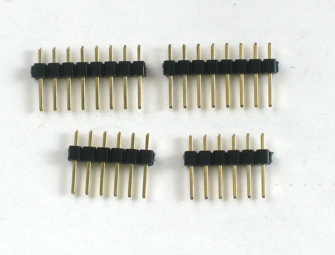
Next, break the 36-pin header strip into smaller sections so that the shield can be placed on the Arduino. You can use pliers or diagonal cutters. Clip off 2-6pin and 2-8pin pieces. |
|
If you're using a Diecimila Arduino, place the 6 and 8 pin headers into the female sockes. If you have an NG Arduino, you can place a 3-pin female header as shown, which will let you use the reset button. |
 |
Place the shield on top of the Arduino so that all of the headers line up.
|
|
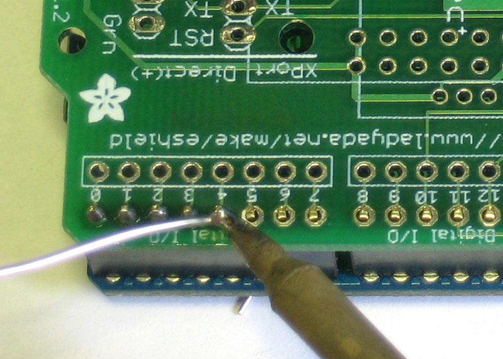
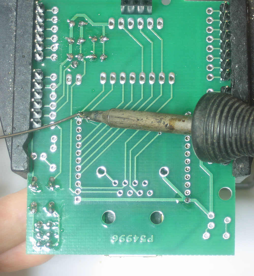
Solder in each pin of the header. If you have an NG arduino, you may want to install a 3-pin female header. This isnt used for non-NG arduinos (like the Diecimilla, Duemilanove, etc)! |
|
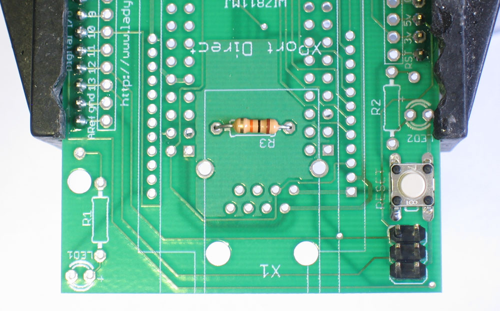
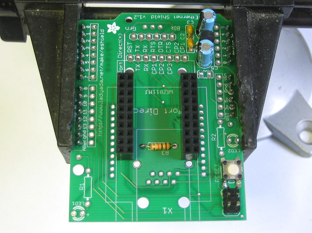
This step assumes you want to use a WIZnet Module If you are using the wiznet module, you will need to install and solder the 10K resistor (Brown Black Orange Gold) Resistors are non-polar so you can install it 'either way' |
|
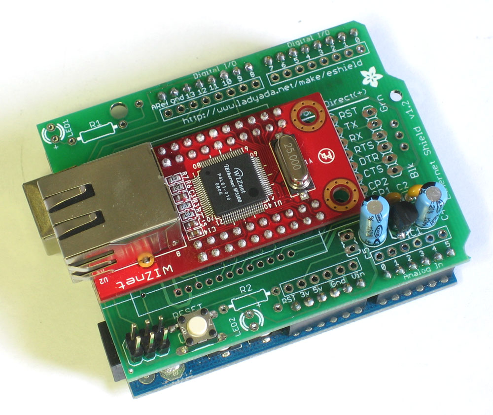
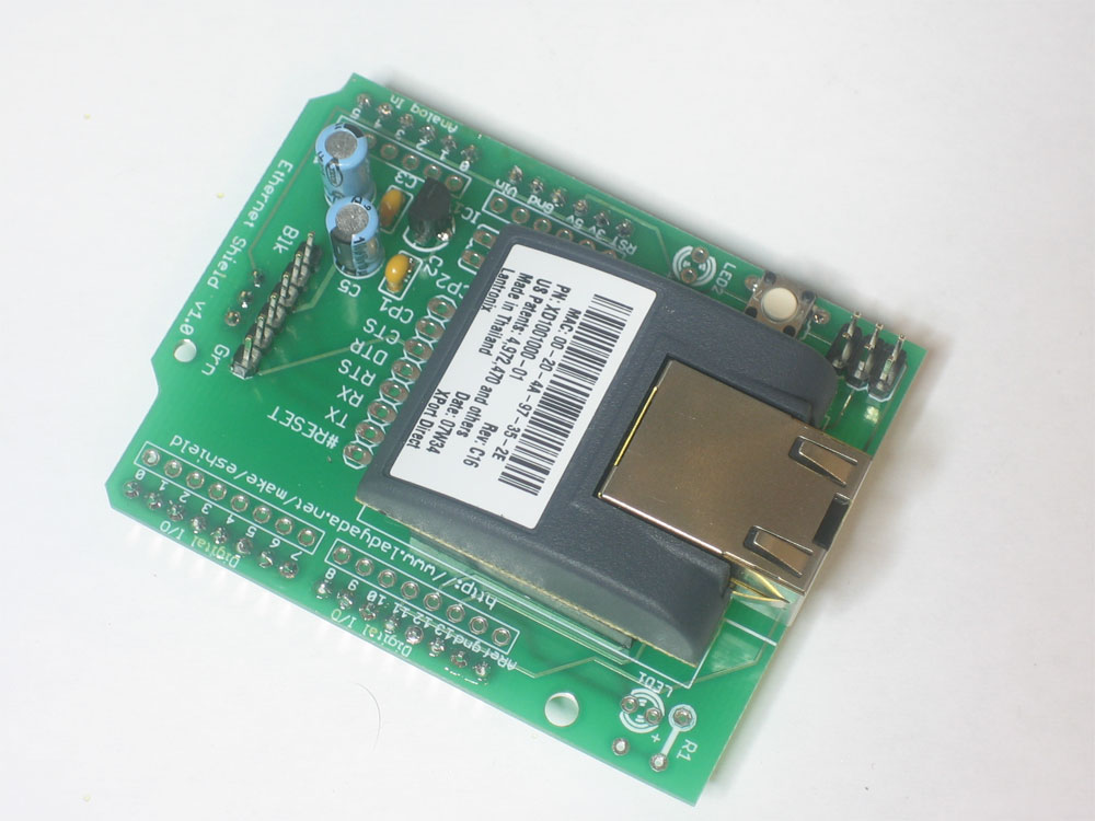
This step assumes you want to use a WIZnet Module If you want, you can solder the WIZnet module straight in. Just line it up so that the ethernet jack sticks out as shown and solder it in |
|
This step assumes you want to use a WIZnet Module Alternately, you can use the 2x10 pin headers that will allow you to reuse the module Place both headers on top, use tape if necessary to keep them in place while soldering all the pins |
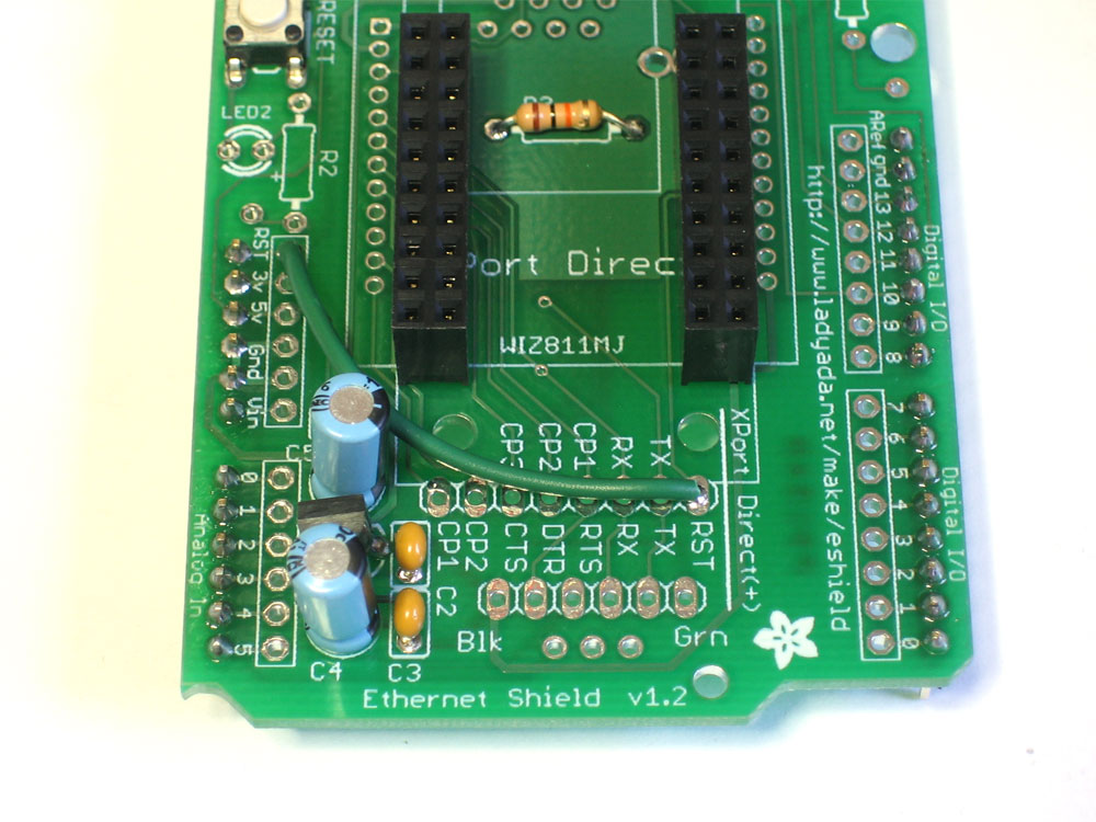 |
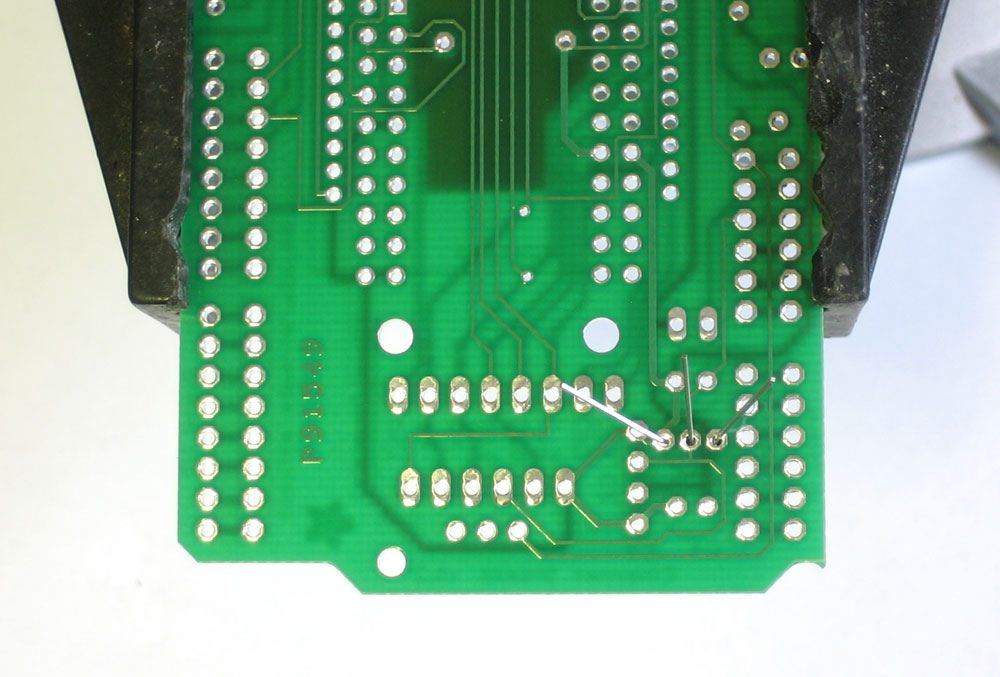
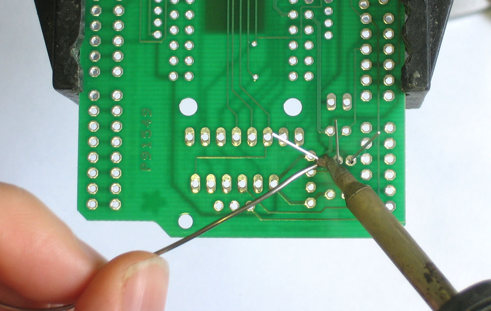
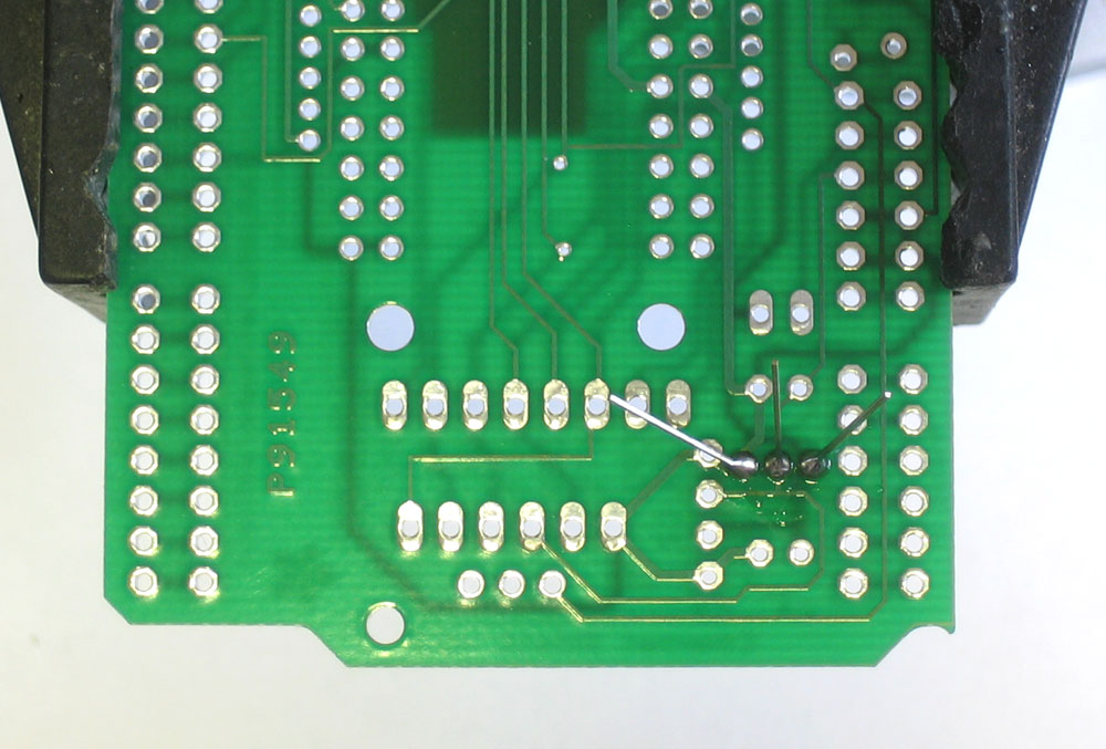
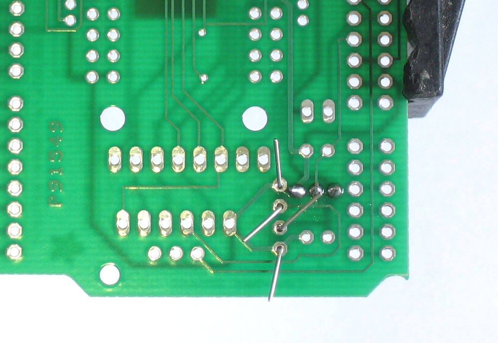
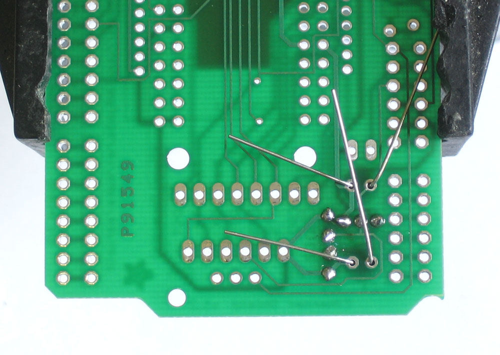
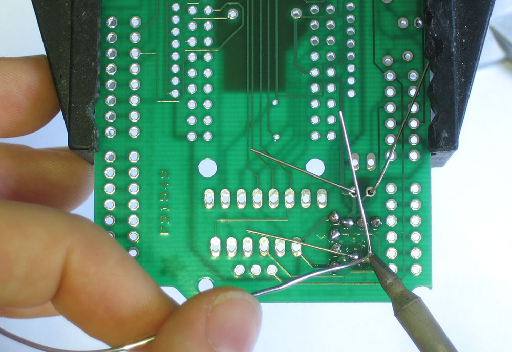
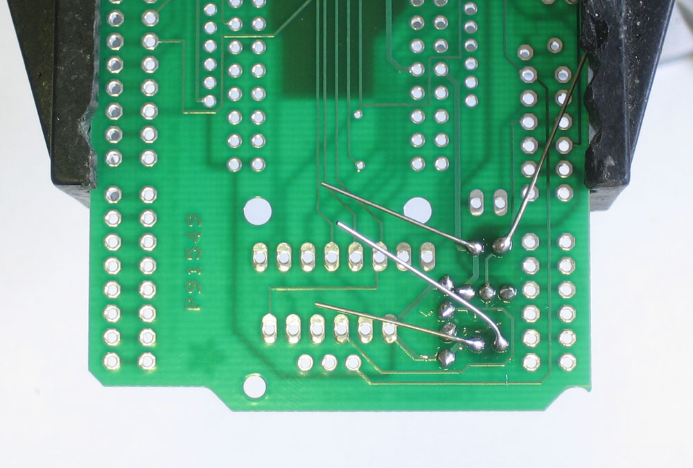
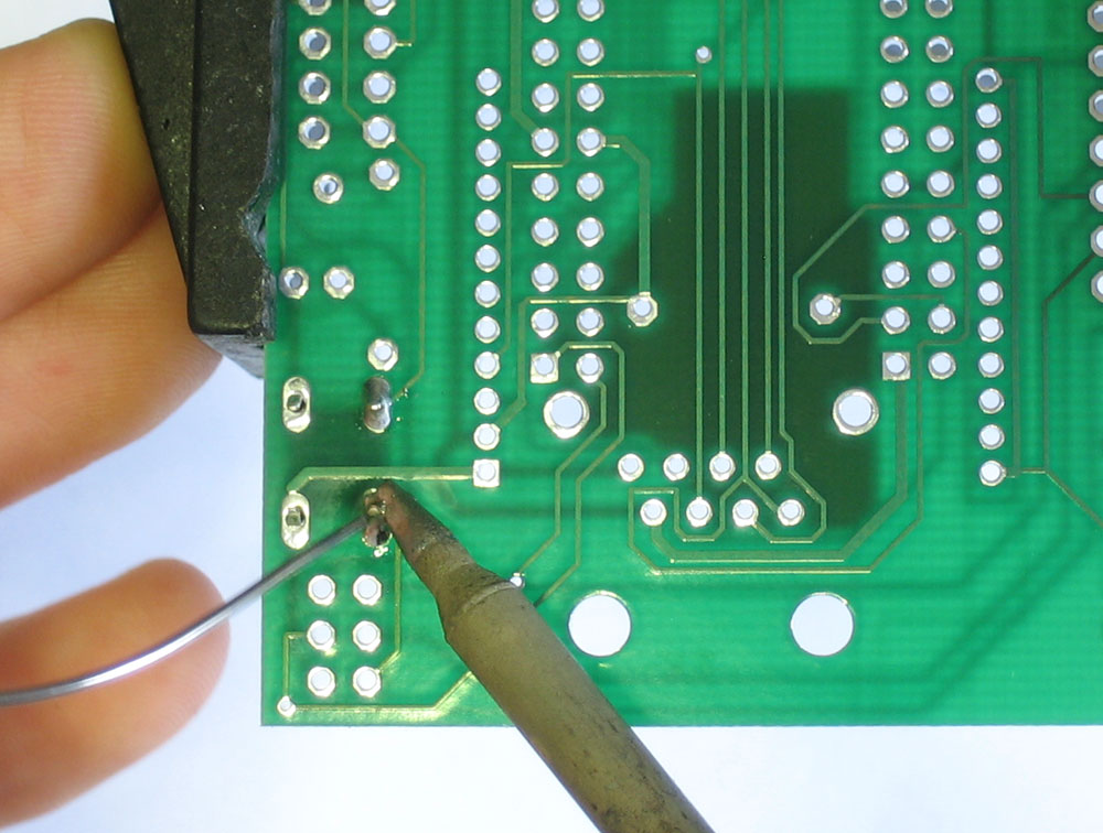
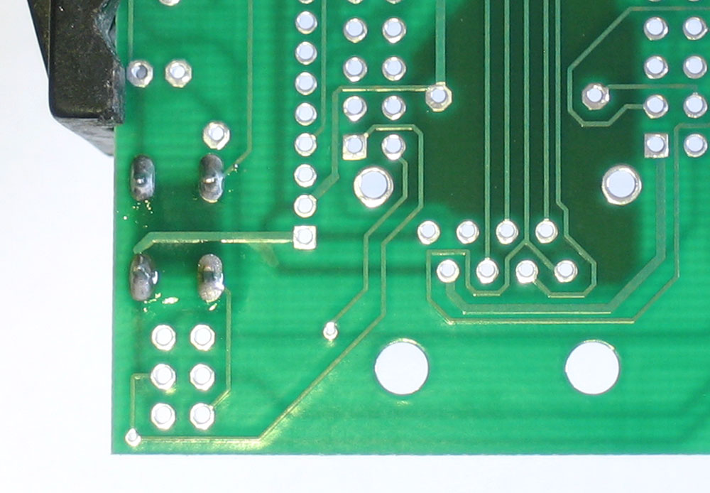
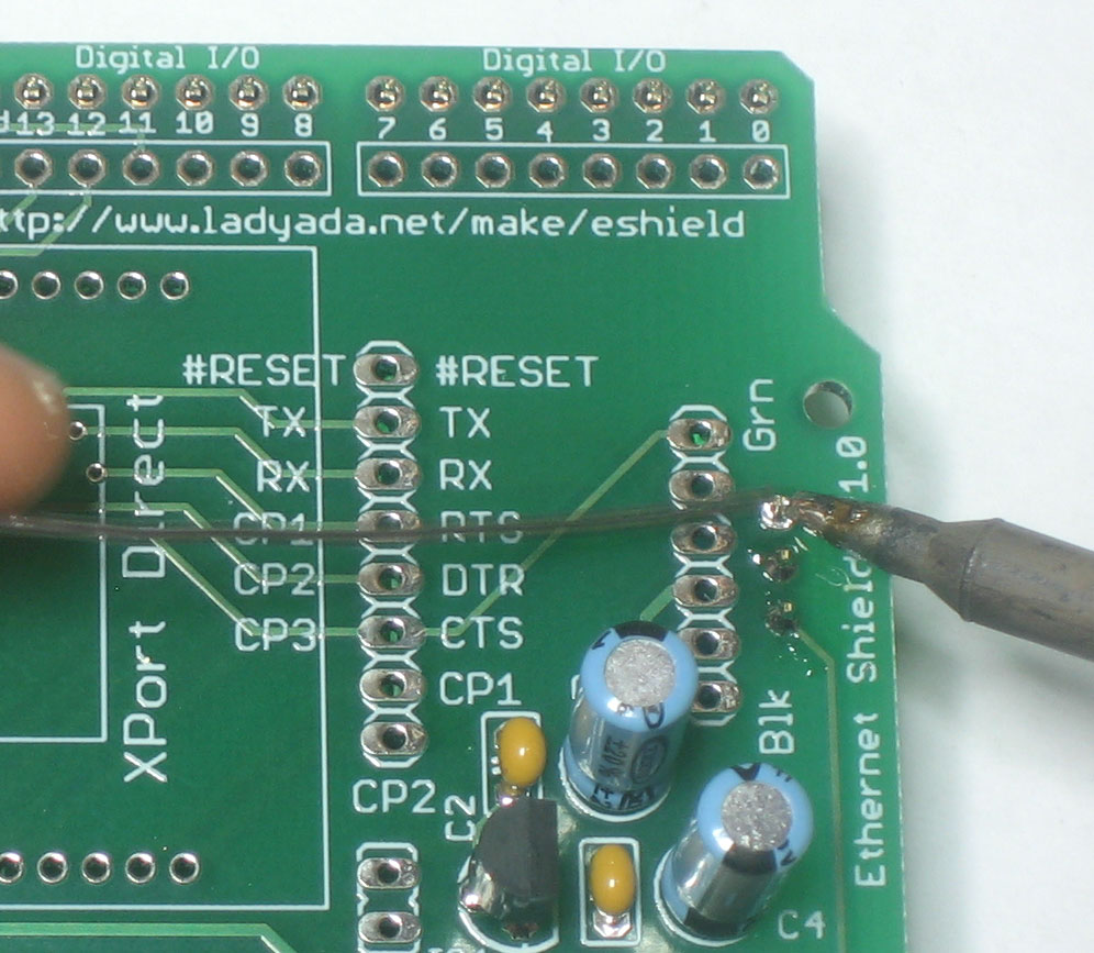
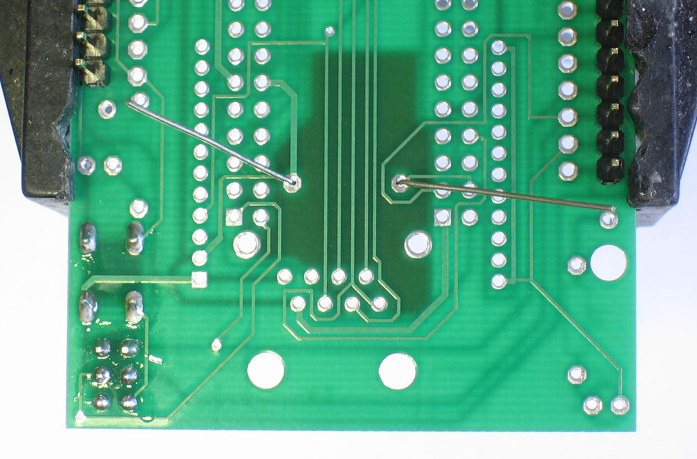
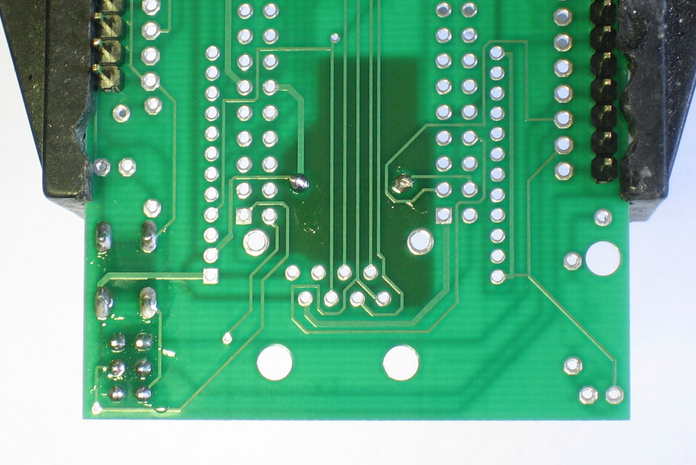
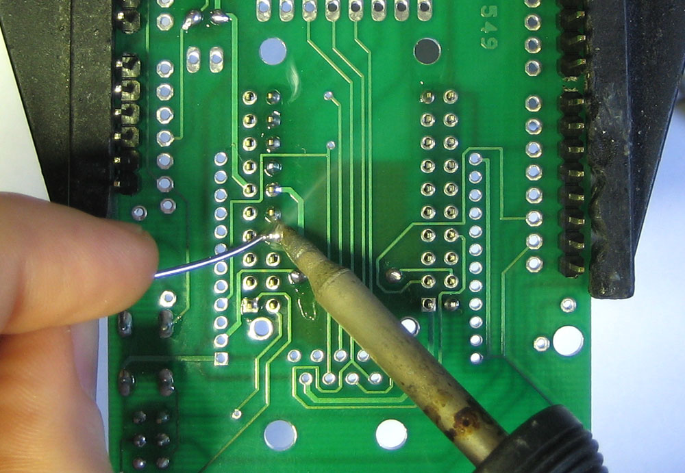
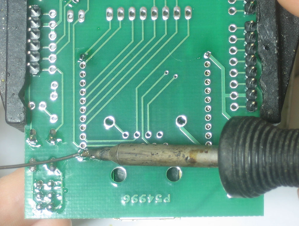
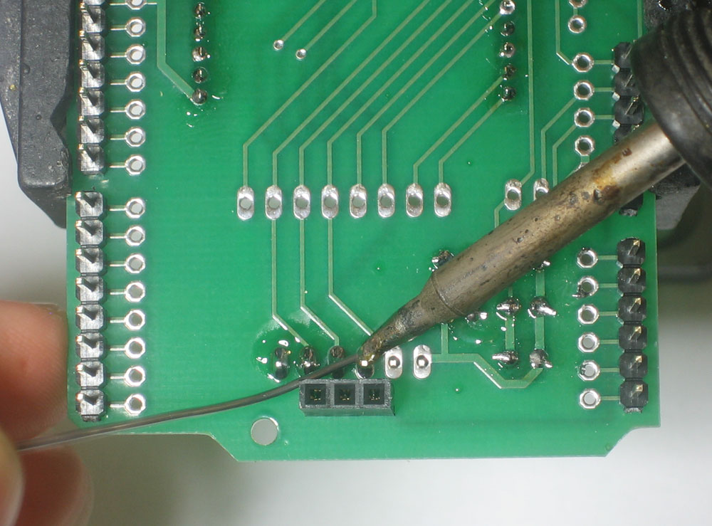
This step assumes you want to use a WIZnet Module Finally, you will want to connect the Reset pin of the module to the Reset line of the Arduino, that way it will be reset when the button is pressed. This is necessary unless you want to reset the module by connecting it to a 'standard' output pin. Now you can plug in the Wiznet module and try out the Ethernet Shield library! |
 |
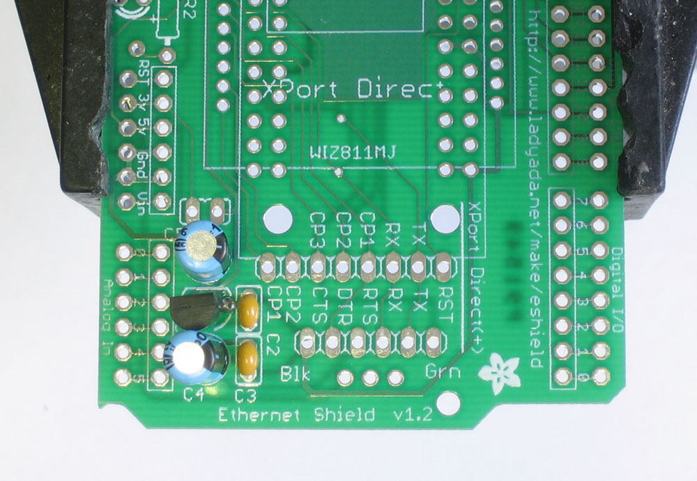
This step assumes you want to use an XPort Direct or Direct+ Place the 2mm 12-pin headers on the XPort Direct |
|
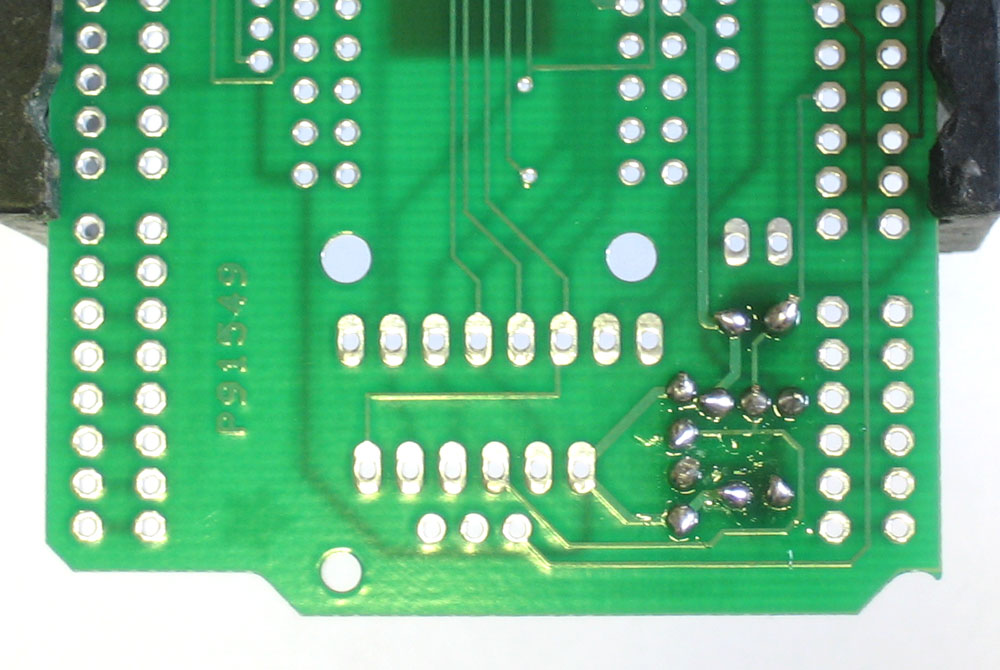
This step assumes you want to use an XPort Direct or Direct+ With the XPort plugged into the headers, place it on the shield and tack the four corners with a small amount of solder. This is to keep the headers spaced properly. |
|
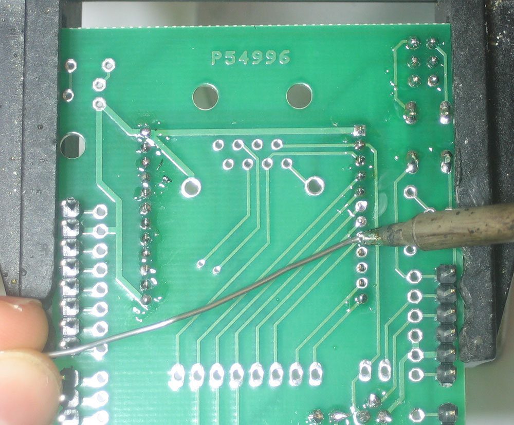
This step assumes you want to use an XPort Direct or Direct+ Remove the module, and complete soldering the header in
|
|
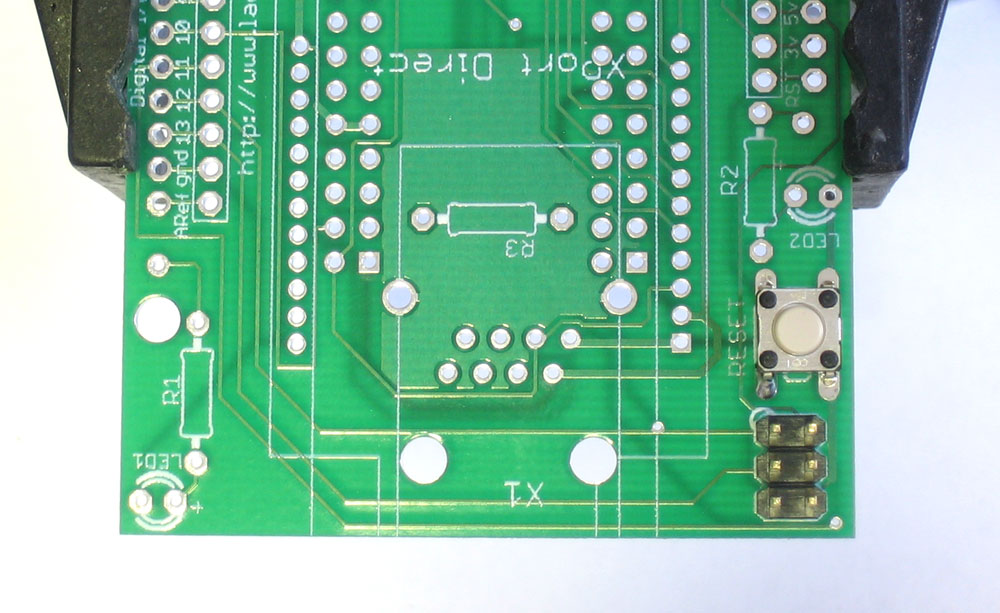
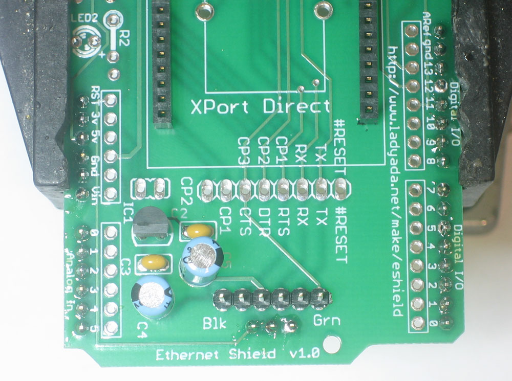
This step assumes you want to use an XPort Direct or Direct+ If you're planning to use a FTDI USB cable with the shield, use the remaining 6-pin header left over from the 36-position strip and place it on the shield right next to the 3.3v regulator, as shown Place the 6 pin headers so that the long part sticks up, and you can solder it from below. |
 |
You're done! Now go read the user manual. |