PLL notes
While the most annoying part of the assembly process, the PLL is the key part of this design. There are multiple test programs and modes for verifying you've 'got it right' so be sure to do them all. The PLL chosen works well, but requires output resistors to convert the 1mA current pump to voltage for input to the microcontroller. Although the UART is tested at the next step, it might not be bad to test that now and then use it to help you debug and play with the PLL.
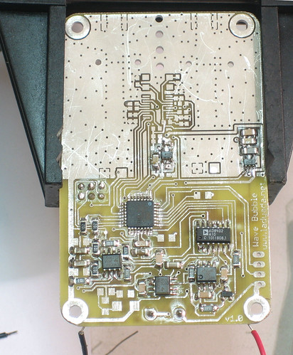
In v1.0, 0.1uF capacitors should be installed 'on top' of the 1206 10K resistors, will be fixed in next revision. Oops.
Parts
| Part # & Datasheets | Name |
Description |
Distributor |
Qty |
Cost |
Total |
|---|---|---|---|---|---|---|
| *LMX2433TM | IC16 |
Dual 3.6/1.7GHz PLL | 1 |
$4.20 | $4.20 | |
| *LP2985IM5-2.5 | IC15 |
2.5V regulator | 1 |
$1.00 | $1.00 | |
| ABMM-10.000MHZ-B2-T | X1 |
10.000MHz Crystal | 1 |
$1.03 |
$1.03 |
|
| 3.9pF 0603 | C60 |
Stabilizer for gain stage | 1 |
$0.06 | $0.06 | |
| 5.6pF 0603 | C61 |
Stabilizer for gain stage | 1 |
$0.06 | $0.06 | |
| 20pF ceramic 0603 capacitor | C81, C82 |
20pF crystal resonant capacitors (you can also use 22pF) | 2 |
$0.10 |
$0.20 |
|
| 100pF 0603 | C71, C72, C74, C78-C80 |
Filter capacitors | 5 |
$0.06 | $0.30 | |
| 0.01uF 0603 | C27, C70, C73, C75 |
Filter capacitors | 4 |
$0.06 | $0.24 | |
| 0.1uF 1206 | C25 |
Filter capacitors | 1 |
$0.08 | $0.08 | |
| 0.1uF 0603 | C76 |
Filter capacitors | 1 |
$0.06 | $0.06 | |
| 1.0uF 1206 | C26 |
Filter capacitors | 1 |
$0.18 | $0.18 | |
| 1.0uF 0603 | C50-C53, C63, C77 |
Filter capacitors | 4 |
$0.05 | $0.20 | |
18ohm 0603 |
R20-R22, R29 |
Power supply filters | 4 |
$0.08 | $0.32 | |
| 50 ohm 0603 | R33, R34 |
PLL feed resistors | 2 |
$0.08 | $0.16 | |
| 10K 0603 | R40, R42 |
PLL output current sinks | 2 |
$0.06 | $0.12 | |
| 10K 1206 | R41, R43 |
PLL output current sinks | 2 |
$0.06 | $0.12 | |
| Total | $3-$9 |
Assembly
 |
Solder in the 2.5V regulator for the PLL |
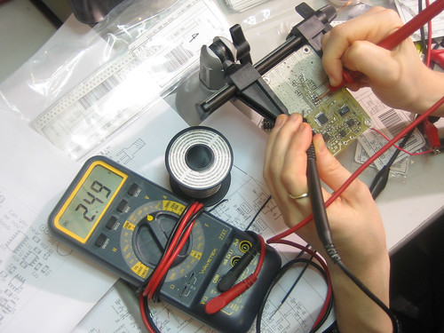 |
Test the output of the 2.5V regulator |
 > > |
Next is the PLL, the more arduous part of the project. |
< 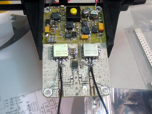 |
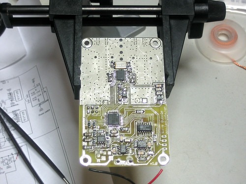
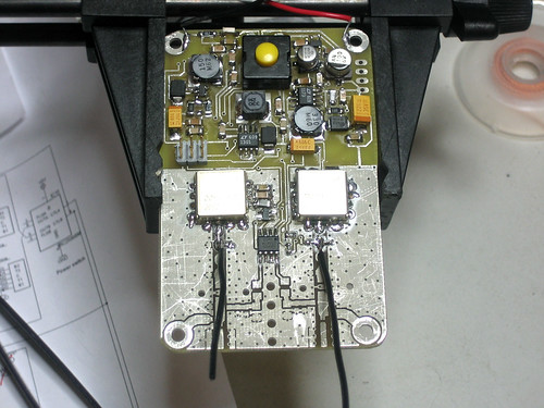
Solder in all of the PLL components, including the feed resistors from the VCOs and the 4 10K resistors (2 on the other side). |
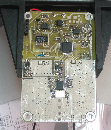 |
For v1.0 there are two fixes: first, solder 2 0.1uF capacitors on top of the 10K resistors from the PLL (to stabalize). Second, the RX/TX lines are swapped. In future revs this will be fixed. |
|
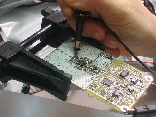
Probe the crystal to verify that the PLL is at least driving it properly. |
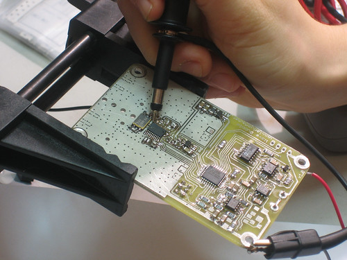 |
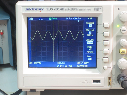
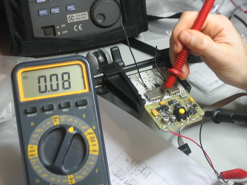
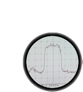
Program in the test_pll1() code. Probe pin 10 of the PLL with a scope or meter and verify you see a 1Hz square wave. This verifies that the PLL is running and is receiving commands. |
|
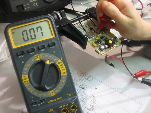
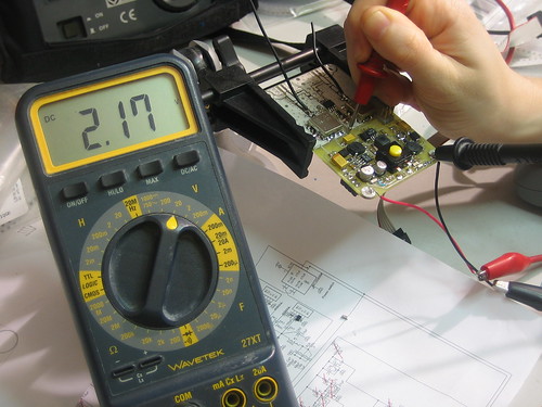
Program in the test_pll2() code. This will set the PLL to 1GHz and 2GHz (for the low and high VCO, respectively) and sweep the VCOs. Now probe the outputs of the PLL (in between the 10K resistors) and note that as the VCO sweeps up, the voltage switches from ~0V to ~2.2V indicating that the PLL is detecting the VCO output and is functioning properly |