So you have this chip, and its programmable. But how do you get your program onto that chip?
Comments? Suggestions? Post to the forum!
When code is compiled into a windows program, its turned into "binary" which means its not human-readable (which is tough for machines to understand), instead it is machine-readable. Under windows, these programs (often called applications or executables) are often named ending with .exe (for example notepad.exe or winword.exe), on Macs, they are often named ending with .App (although the Finder hides it).
For microcontrollers, binary files end in .hex (short for Intel Hex Format) There are other formats possible, but this is pretty much standard.
Your compiler will generate a .hex file from code, and then all you have to do is transfer that .hex program to the chip!
As discussed in What is it?, the AVR chip has a small amount of flash memory in it. That memory is where the program is stored. When the chip starts up (you give it power) it starts running whatever program is in the flash. So all we have to do is figure out how to write to that flash
A good way to think about flash is to examine it as you probably are familiar with it. Flash storage is also used in MMC/SD cards, which are commonly used in MP3 players or digital cameras. If you look at the bottom of a card, you'll see little gold fingers. These are the interface pads.
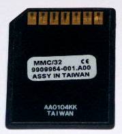
Back of Multi Media Card. By Andrzej Barabasz.
If you look up in the MMC card specification, you'll find out that these are what the 7 pins are for. (SD/high speed cards may have extra pads, but that standard was added later because the existing standard was considered too slow for big megapixel cameras)
| Pin # | Pin Name | Pin Function |
|---|---|---|
| 1 | #CS | Chip Select (Activate) |
| 2 | SI | Serial In |
| 3 | GND | Ground |
| 4 | VCC | Power |
| 5 | SCK | Data Clock |
| 6 | Not connected | Not connected |
| 7 | SO |
Serial Out |
The power and ground pins are used to connect power to the chip. The Chip Select pin is used to tell the chip that it should wake up, Serial In pin is used to send data to the card, Serial Out is how data is sent from the card and Data Clock is how we tell the card how fast we want data to be stored or retrieved. Data is pushed in an out of the chip one bit at a time, so if the clock rate is 100KHz that means that 100,000 bits are transferred per second.
When you want to retreive or store data on a flash card all you have to do is stick the card into a flash card reader. The reader then has a driver on your computer which lets you simply drag files onto a picture on your screen and it does all the hard work of sending the data to the card.
OK, so what does this have to do with a programmer? Well, the microcontroller is like the flash card and the card reader is like the programmer. When you stick the chip into the programmer (or, more likely, the programmer cable into the circuit board that contains the chips) it allows the software on your computer to talk to the chip through the programmer. Usually you can just give a simple command like 'send this program over' and the programmer will do all the hard work of programming and verifying the data
Every AVR has a set of pins that are the programming pins, you just have to connect the programmer to those pins in the right order and presto you are ready to program it. Unfortunately, nearly every chip has a different pinout so its imperative that you look in the datasheet for the correct pins.
For example, I'm a big fan of the ATtiny2313 chip, so lets open up the 'summary' datasheet (its only a dozen pages long instead of the standard 250. The first page has all sorts of information about what is in the chip.
Quick Quiz : How much EEPROM does the chip have? How about flash storage? RAM?
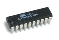
The second page has pinouts. We will be dealing with the PDIP package (Plastic Dual In-line Package) which is the kind that looks like this:
The pinout is reproduced here
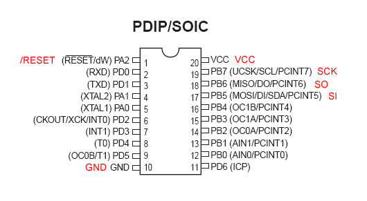
The chip has 20 pins. Look carefully and you'll notice 6 of these pins are equivalent to the SD/MMC card pins. There is a power pin (VCC) and a ground pin (GND), there is also an SCK pin (its called UCSK for some reason) a Serial Out pin (MISO - Master In Serial Out ) and a Serial In pin (MOSI - Master Out Serial In). The only thing is doesnt have is a /ChipSelect pin. Instead it has a /RESET pin, which acts in a similar way. When the /RESET pin is at a postive voltage (the same voltage as VCC) the chip runs the program, when the /RESET pin is at ground (the same voltage as GND) then the chip stops and listens for programming instructions on the programming pins.
All SD cards have the same fingers in the same place so that when you slide it into the card reader, the right pads are connected. AVR programming works in a similar way. Instead of pads, the chip is often placed in a circuit board which has header pins that the progammer plugs into, the header pinout is standardized so that any programmer can be used once the header is wired up correctly.
There are two standards for AVR in-system programming:
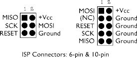
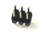
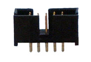
The left is the 6-pin header standard, the right is the 10 pin standard, the headers look like this:
Here is an example photo showing what it looks like when the chip is wired up with a 6-pin header
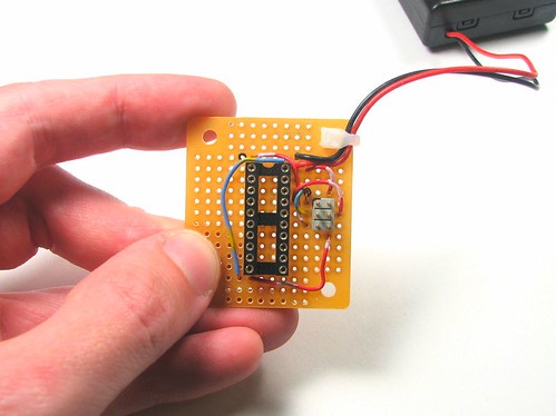
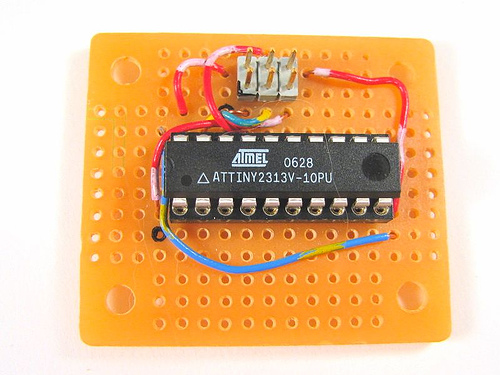
Photo courtesy EvilMadScientistLabs
The black mark on the PCB and header indicate pin #1. You can trace the wires to correllate the pins of the chip to the pins of the header and verify for your self that this breadboard is correct.
Exercise: Verify the pinout for this target board
To learn how to make a 'target board' that lets you program AVRs (in particular, said ATtiny2313) please visit EvilMadScientistLab's tutorial. Its quite easy and will cover some of the same material.
Now that you know how programming works, its time to chose your weapon programmer.