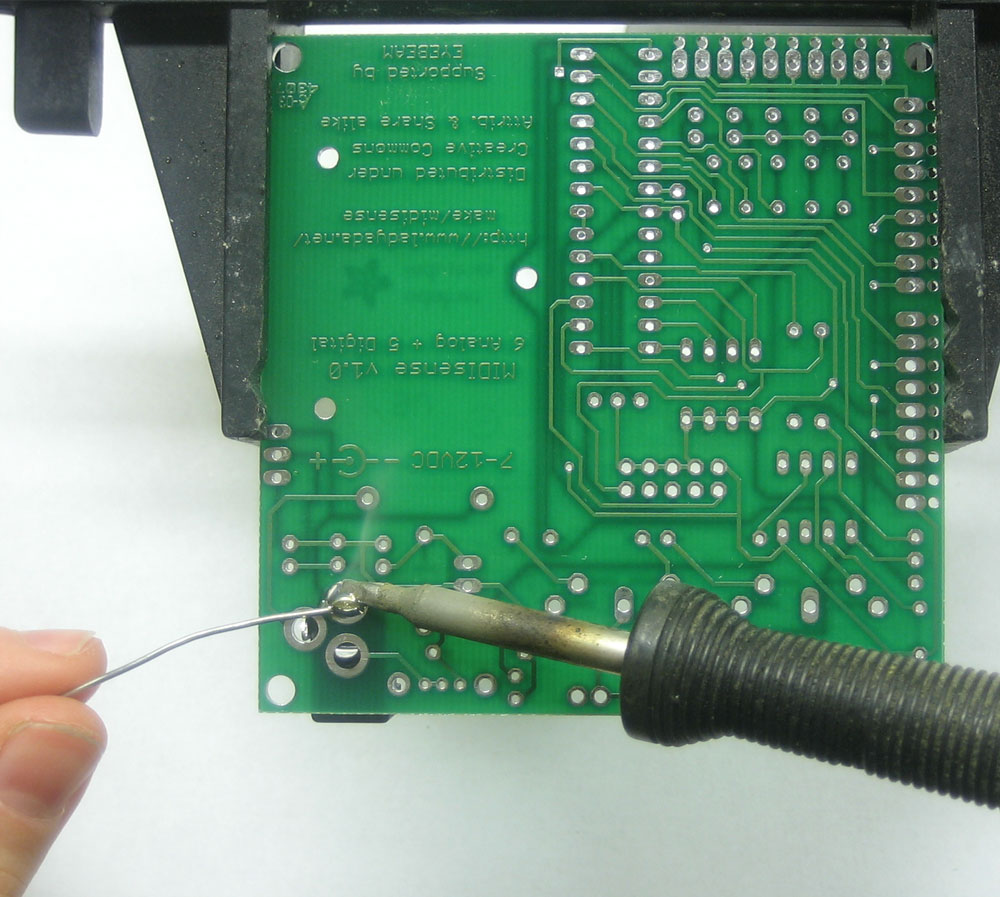
Time to solder the kit together! If you've never soldered before, check the Preparation page for tutorials and more.
Some web browsers (basically, IE) do not like my website so much and load the photonotes slowly. So, if you are wondering where the rest of the instructions are, either wait a while and IE will eventually display it (below here). Or download Firefox/Safari which does not have this problem!
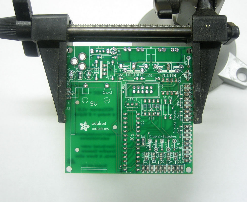 |
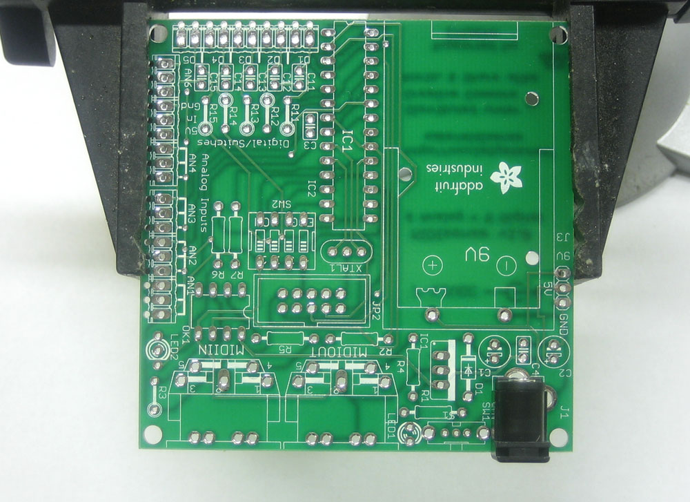
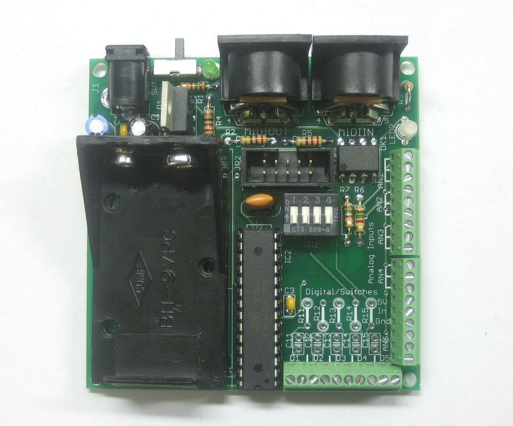
Before you start, read the prep page to make sure you have all the parts and tools necessary! Heat up your soldering iron to 700deg F and place the ADIO kit circuit board in the vise |
|
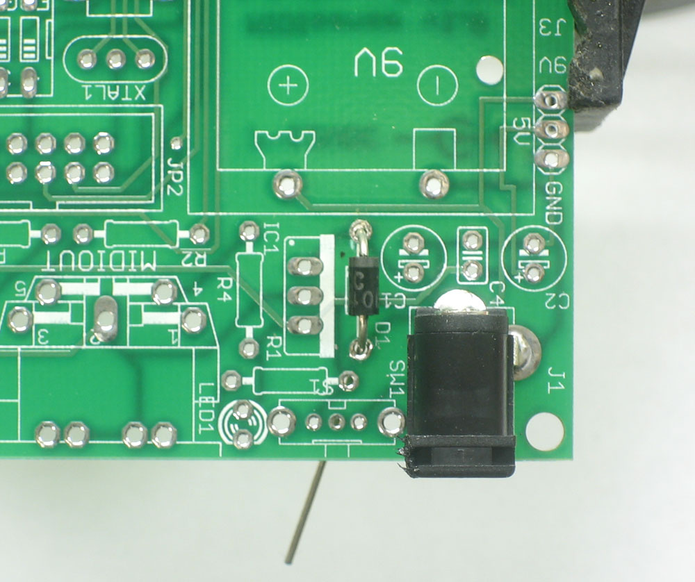
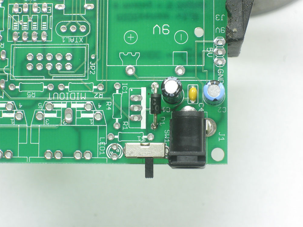
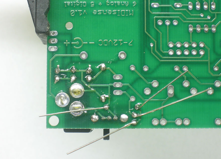
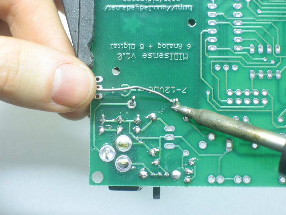
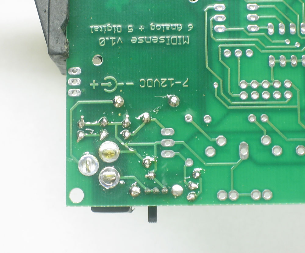
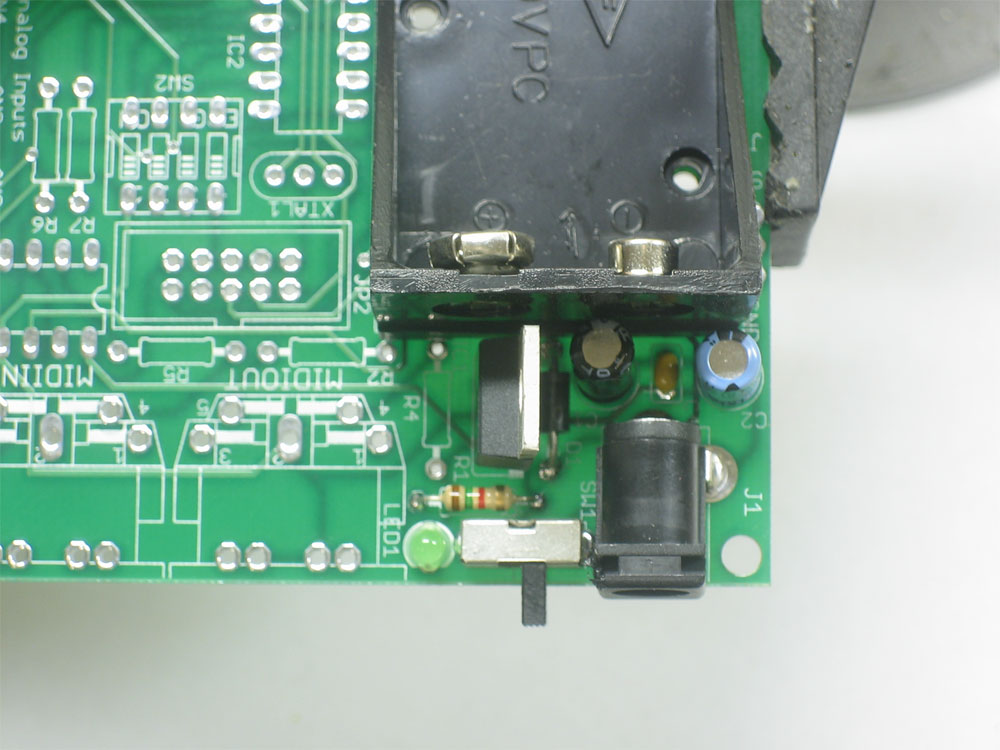
The first part to be soldered is the 2.1mm DC jack. This allows you to plug in a wall adapter. Even if you're not planning to use a wall adapter (say you only want a 9V battery) you still have to solder this part in! Place the part as shown, in the bottom right corner. Turn over the PCB and using the soldering techniques you learned in the prep section, fill all three holes with solder. Make sure your iron is hot, and you have rosin-core solder. Press the side of the iron tip against both the pin and metallic hole and after a few seconds, poke the solder into the joint formed between the pin and the iron. Fill the holes completely, as this will keep the jack from 'cracking' loose from use. |
|
The next item to be soldered is the diode D1. This diode only lets electricity in one way. It will protect the circuitry from plugging in an incorrect DC adapter (one that is negative instead of positive, or AC instead of DC). Make sure the white stripe on the diode matches the white stripe in the picture silkscreened onto the PCB. Otherwise the diode will have the wrong polarity and the kit wont work at all! The diode should lay flat against the PCB, then bend the legs out a bit so that it stays in the PCB when you flip it over. |
|
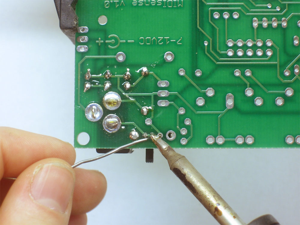
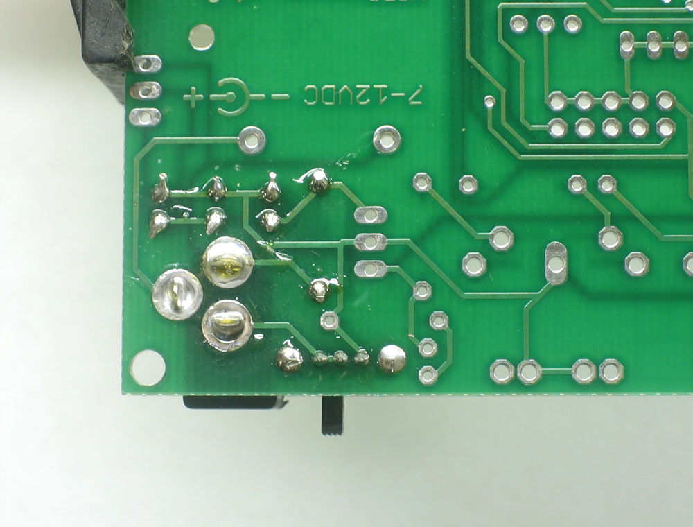
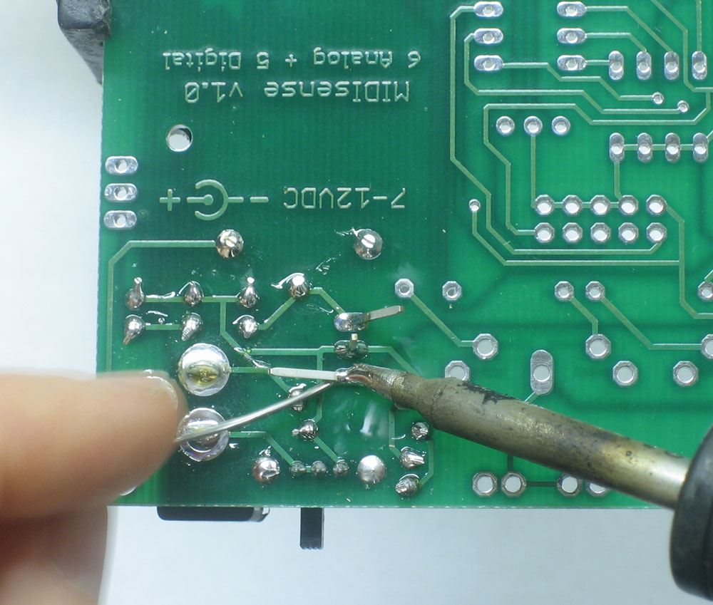
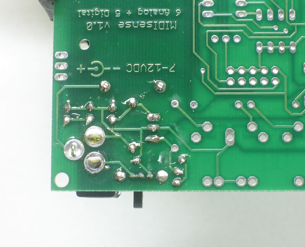
Flip the PCB over, solder in both leads. |
|
Use your diagonal cutters to snip off the leads of the diode, just above where the solder point ends. |
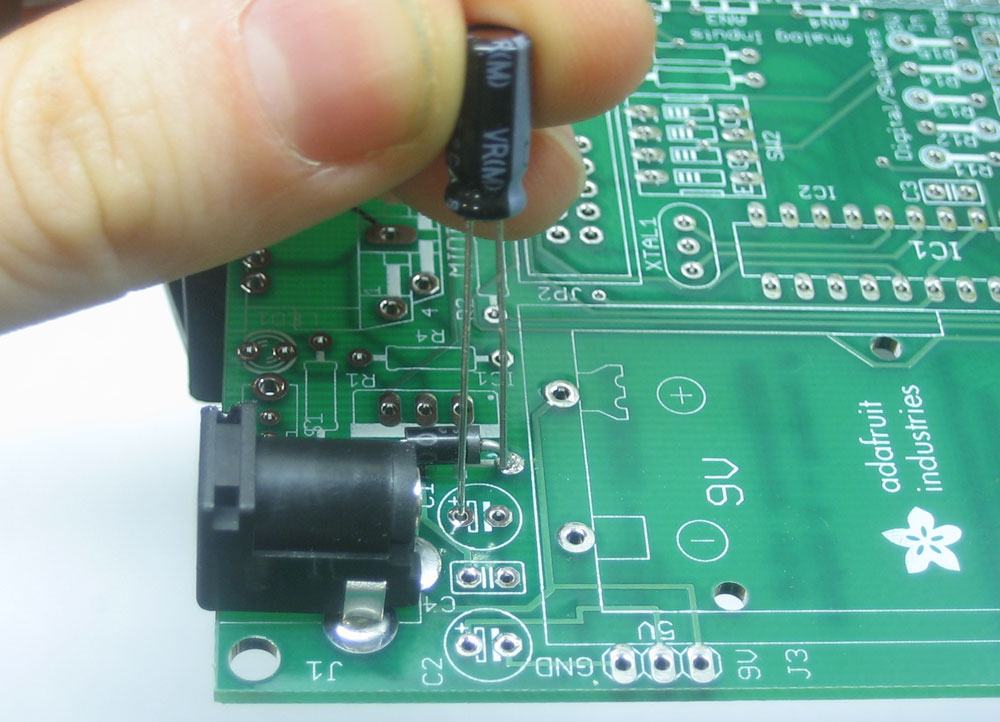 |
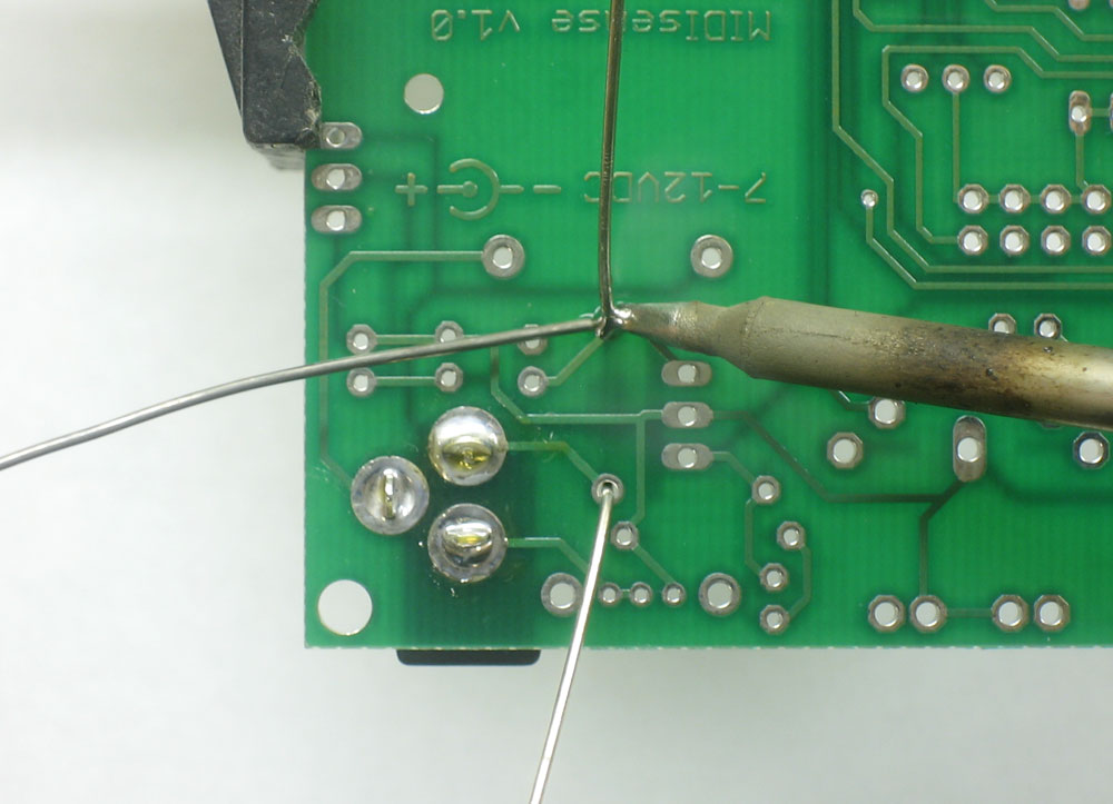
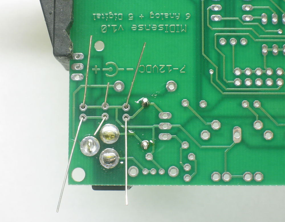
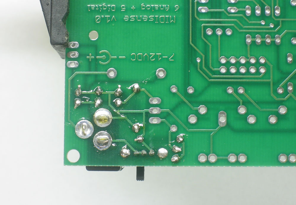
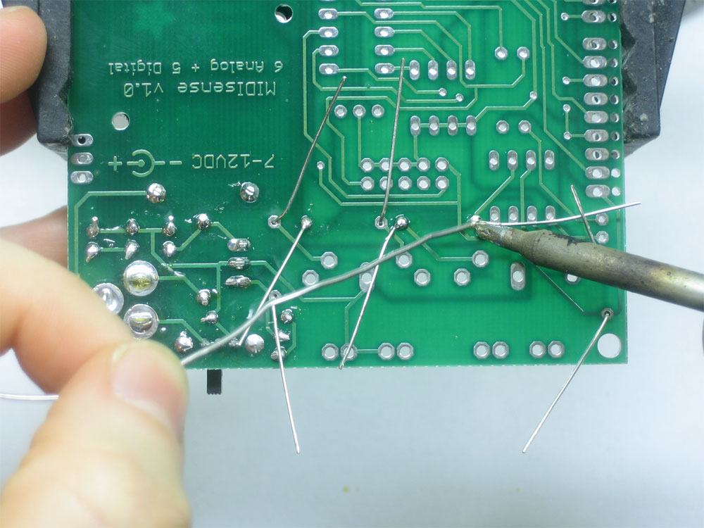
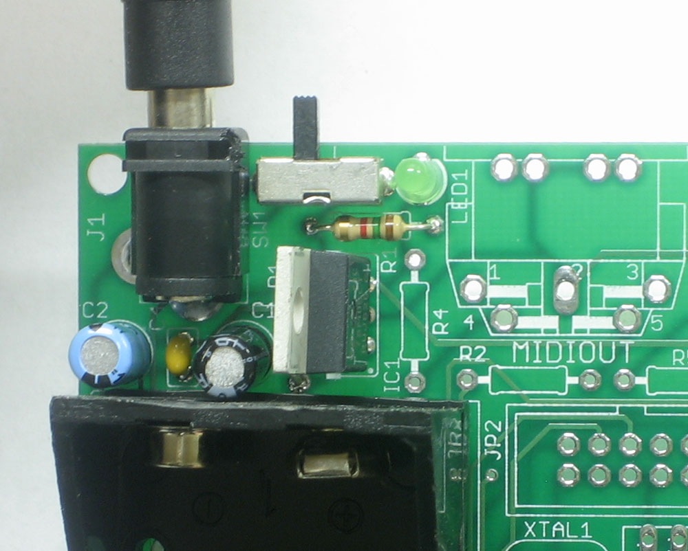
Next its time to install the 9-12V input capacitor C1. This devices smoothes out the voltage coming in from the DC jack/9V battery. This way any spikes or noise that come from the DC adaptor or battery will not be transferred to the circuit. Electrolytic apacitors are directional, and only work if installed the correct way. The longer lead of the capacitor (the + lead) goes in the hole marked with a small +. You can see in the image that here it is the left leg. |
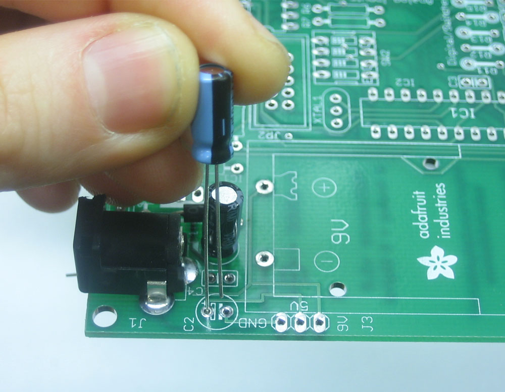 |
Next its time to install the 5V input capacitor C2. This devices smoothes out the voltage coming out of the 5V regulator. This way any spikes or noise that come from the 5V regulator are quieted down. Electrolytic apacitors are directional, and only work if installed the correct way. The longer lead of the capacitor (the + lead) goes in the hole marked with a small +. You can see in the image that here it is the left leg. |
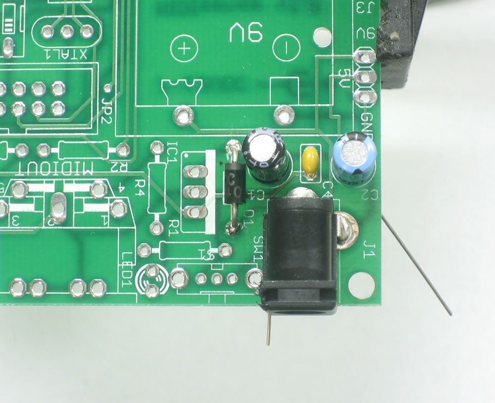 |
Finally install the ceramic capacitor C4. This is a 5V capacitor too, and its especially good at smoothing out high frequency spikes (electrolytic capacitors are only good for low frequency noise such as 60Hz) Ceramic capacitors are not polarized so it can go in either way. Double check your board against the photo to make sure you have the right polarity of capacitors. |
|
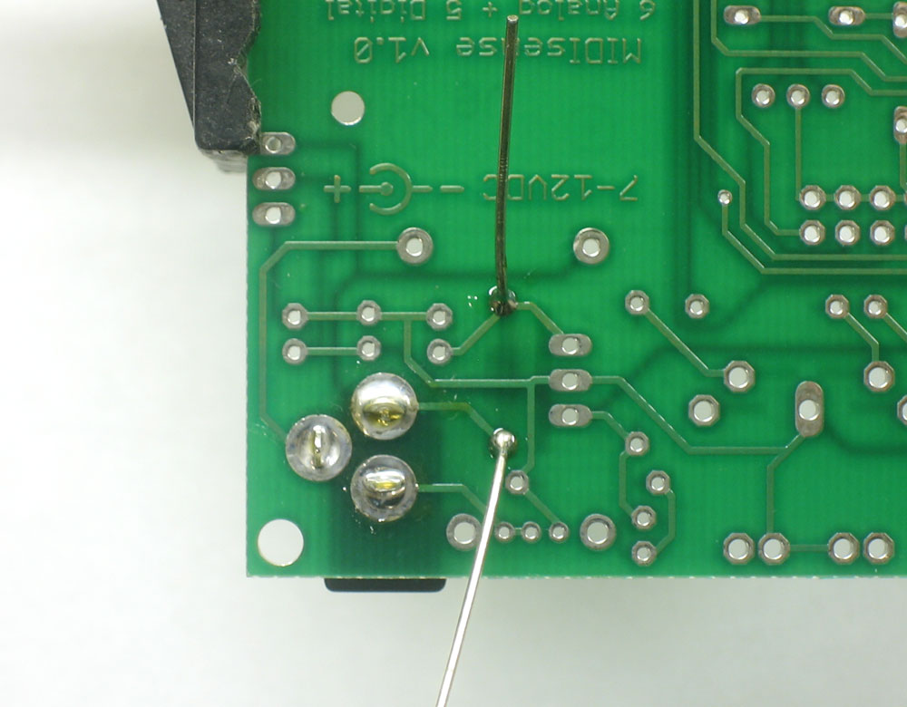
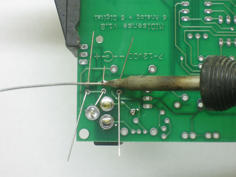
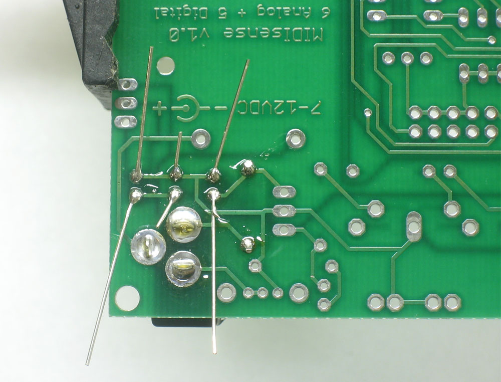
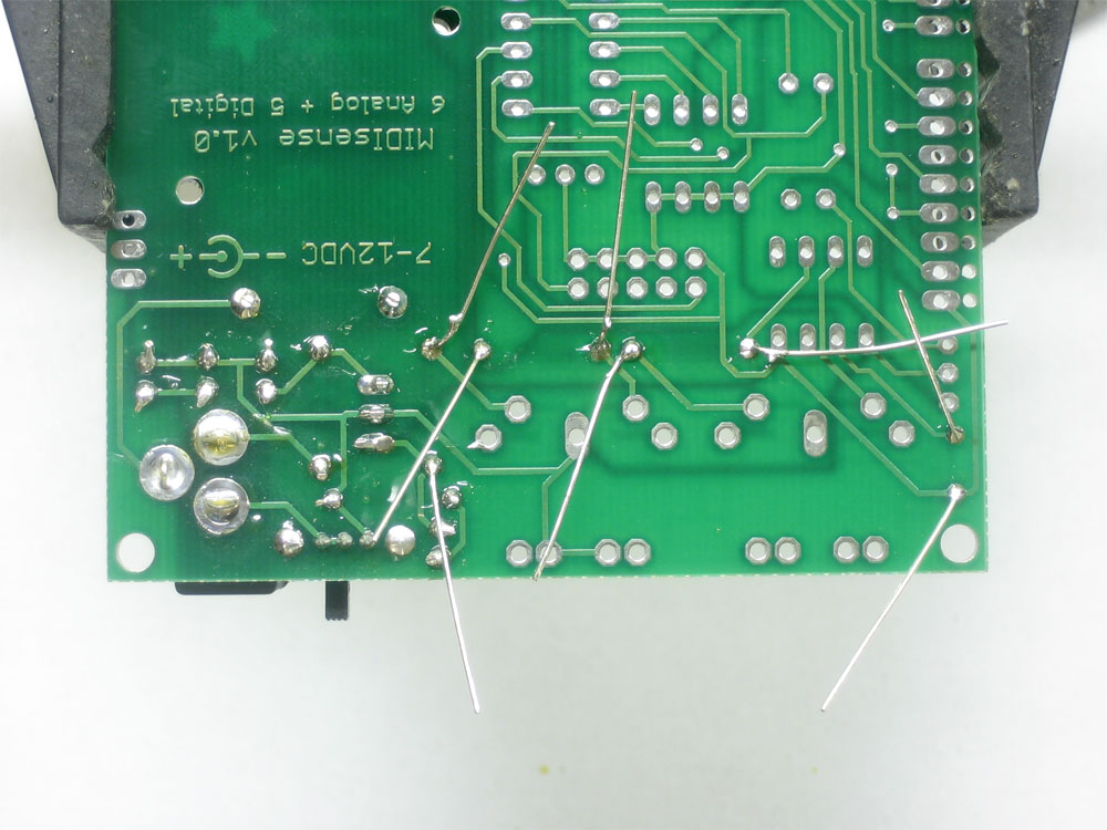
Flip over the board and solder in the three components. |
|
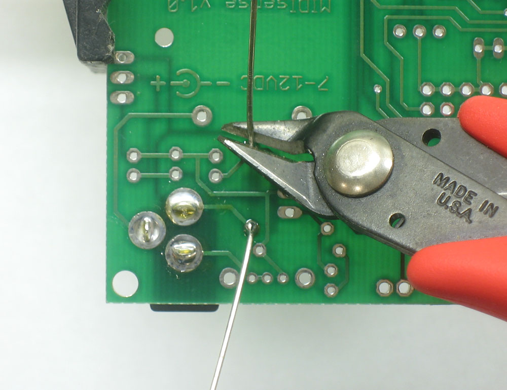
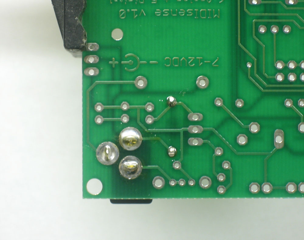
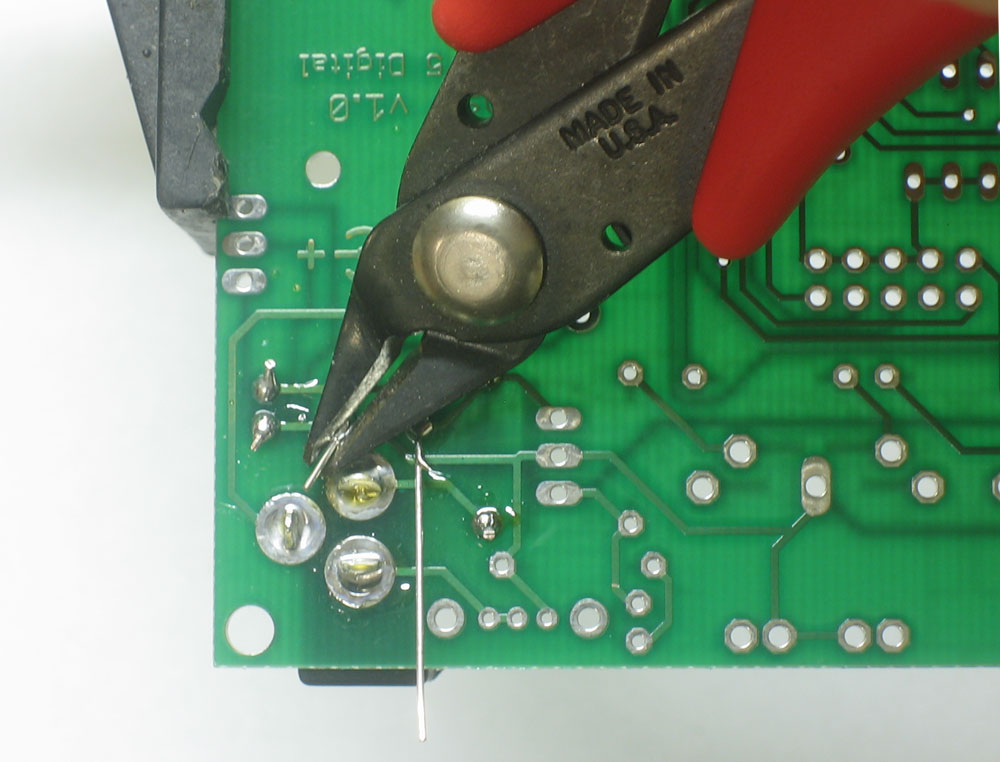
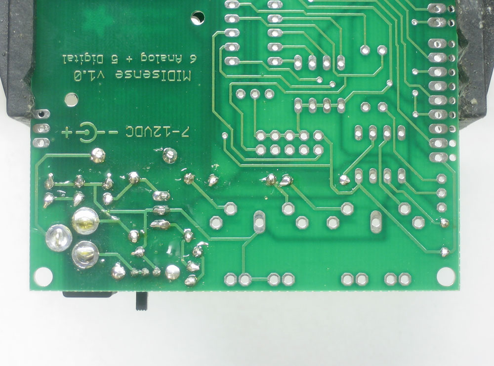
Then clip the leads as you did before, so that there are no stray wires. |
|
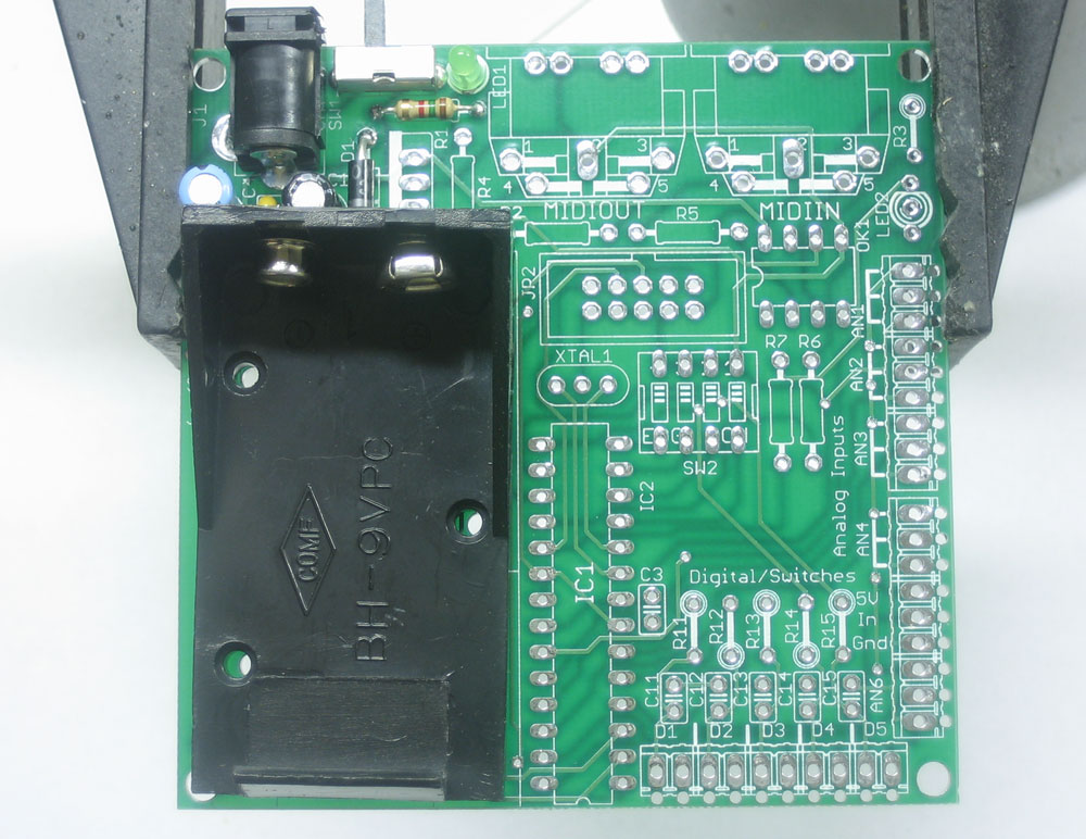
Next install the power switch SW1 as shown. It should fit snugly. Turn over the PCB and solder in the pins. They are somewhat close together so make sure you dont accidentally put too much solder on. Make sure you also solder in the two 'mounting pins', the 2 larger holes. They will provide mechanical stability to the switch |
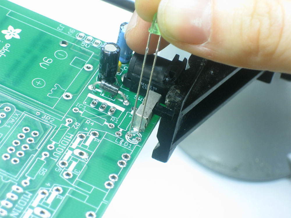 |
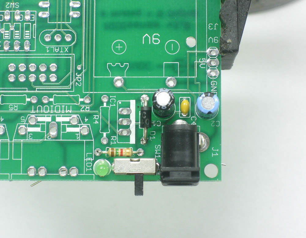
Next its time to install the tiny 'power good' LED1 that will indicate whether the kit is powered up. The LED may be red or green. Either way, LEDs (Light Emitting Diodes) are just like normal diodes and thus must be inserted the correct way. The long lead (which is +) goes on the left in the photo here. |
|
Next, insert the LED choke resistor R1 next to LED1. This resistor determines how bright the LED is. we use a 1.0K or 1.5K resistor, which seems to be a good brighness. Resistors are non-polarized so you can insert it either way. Then turn the PCB over and solder in both the LED and resistor and clip off the leads when done. |
|
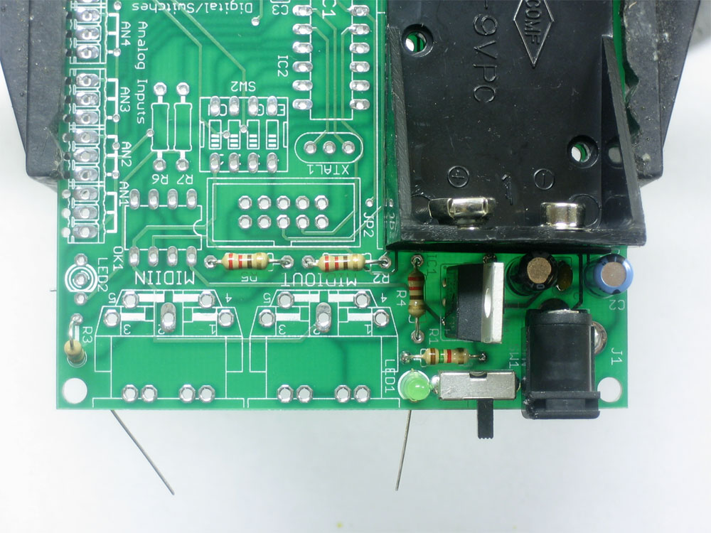
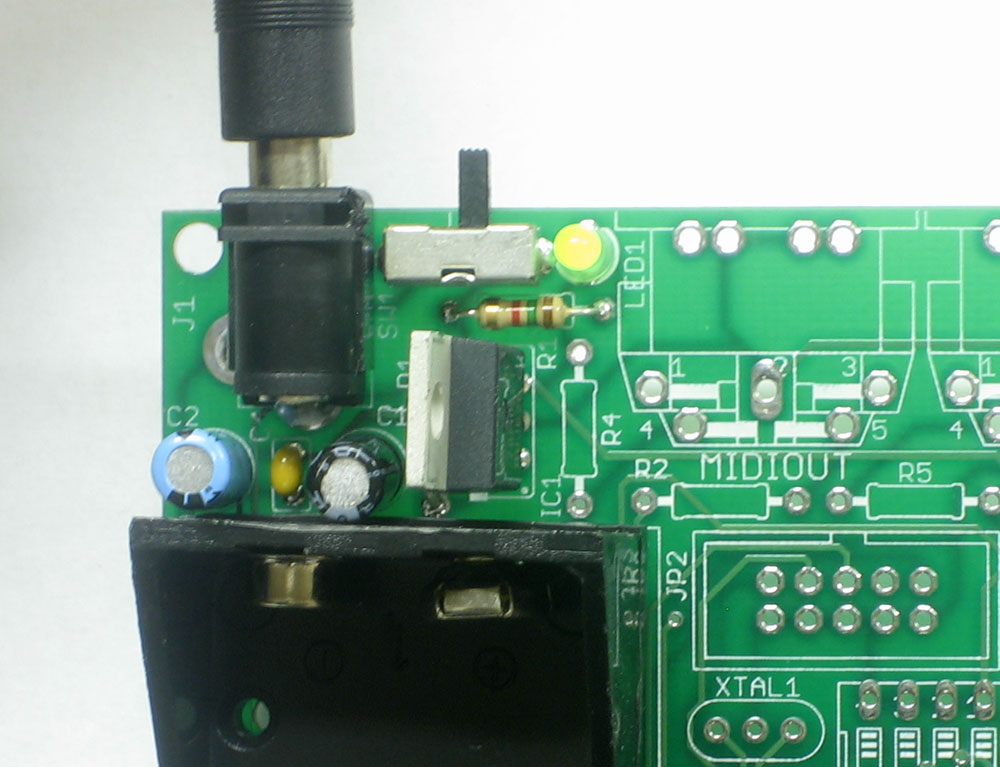
If you're planning to power the MIDIsense with a 9V battery, you can use the battery holder, seen here. Simply place and solder it in. You can use the 2-56 screw, washer and hexnut on one of the holes to keep it from shifting around (not shown) |
 |
Next is the 7805 5V regulator, IC1. This is the device that turns the 9V from the battery (or wall adapter) into 5V, which is what the microcontroller needs. It has three pins and needs to go in the right way to work, so make sure it is placed as shown. The metal 'heat sinking' tab goes on the same side as the thick white line silkscreened on the PCB. |
|
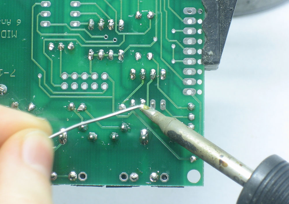
Turn over the board and solder/clip the regulator pins. |
 |
Finally its time to test out the 5V circuitry. Plug in a 9VDC wall adapter. With the switch to the left, the green LED should be off and there should be no smoking, heating up, or weird smells |
 |
With the switch to the right, the green LED should be on and there should be no smoking, heating up, or weird smells. This test verifies that the voltage regulator system works and is safe for use. Once you're done checking the regulator, unplug the wall wart and/or remove the 9V battery |
|
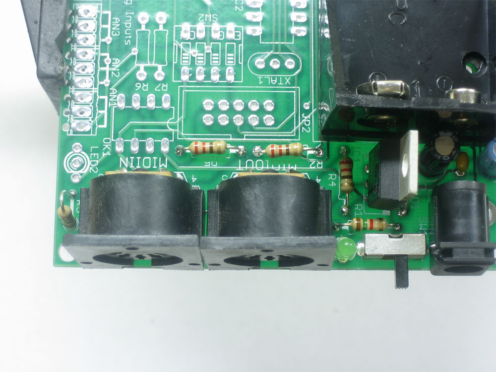
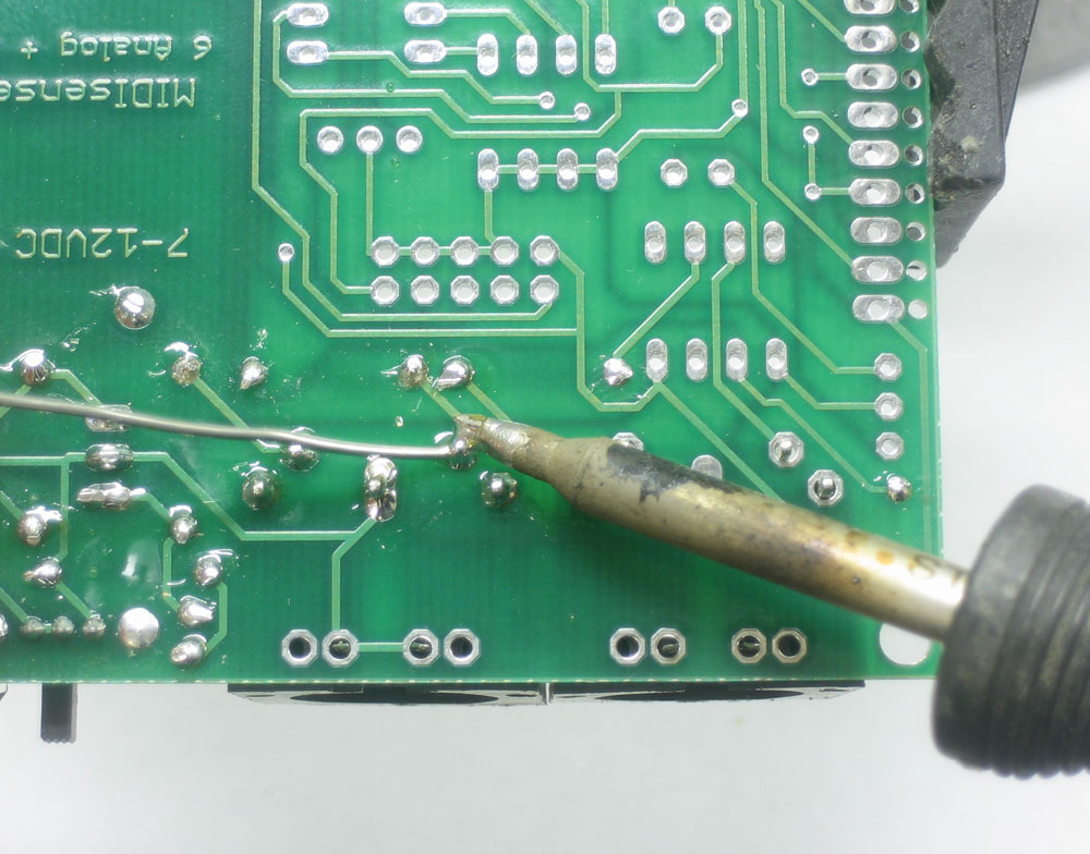
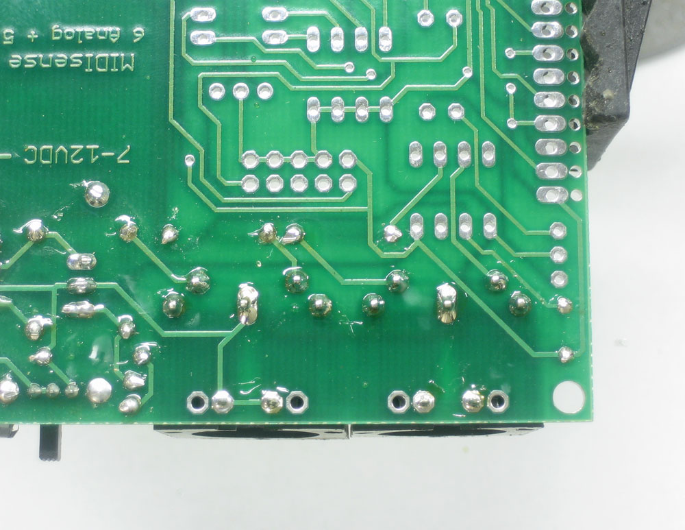
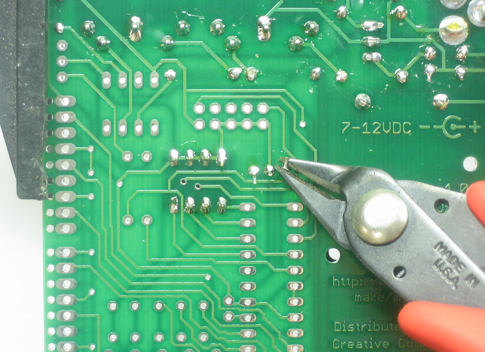
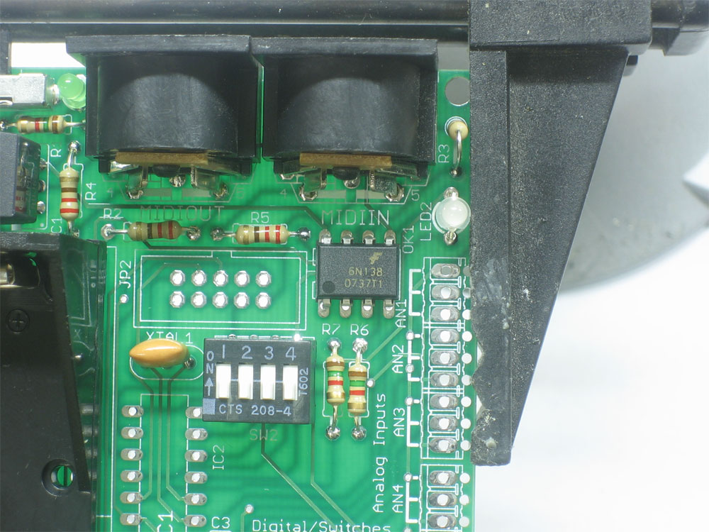
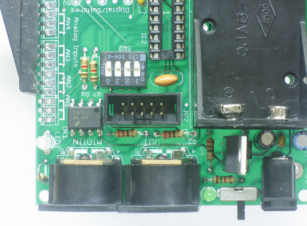
Next its time to solder in the 4 220ohm MIDI resistors R2, R3, R4, R5. Remember that resistors are not polarized so they can go in either way. Place, solder and clip all four resistors |
|
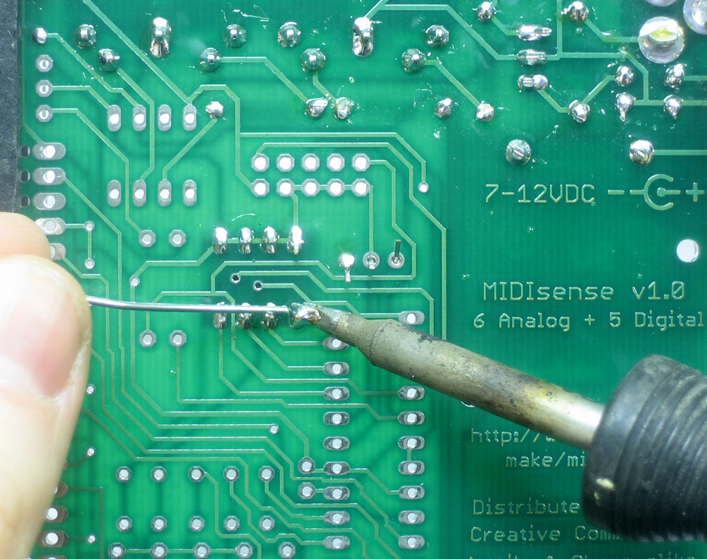
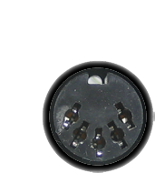
Next are the MIDI jacks, one for input and one for output. Place both and solder all 7 pins. To help keep the jacks in place, it may help to place the jacks, then solder one pin from above so that they are 'tacked' in place. |
|
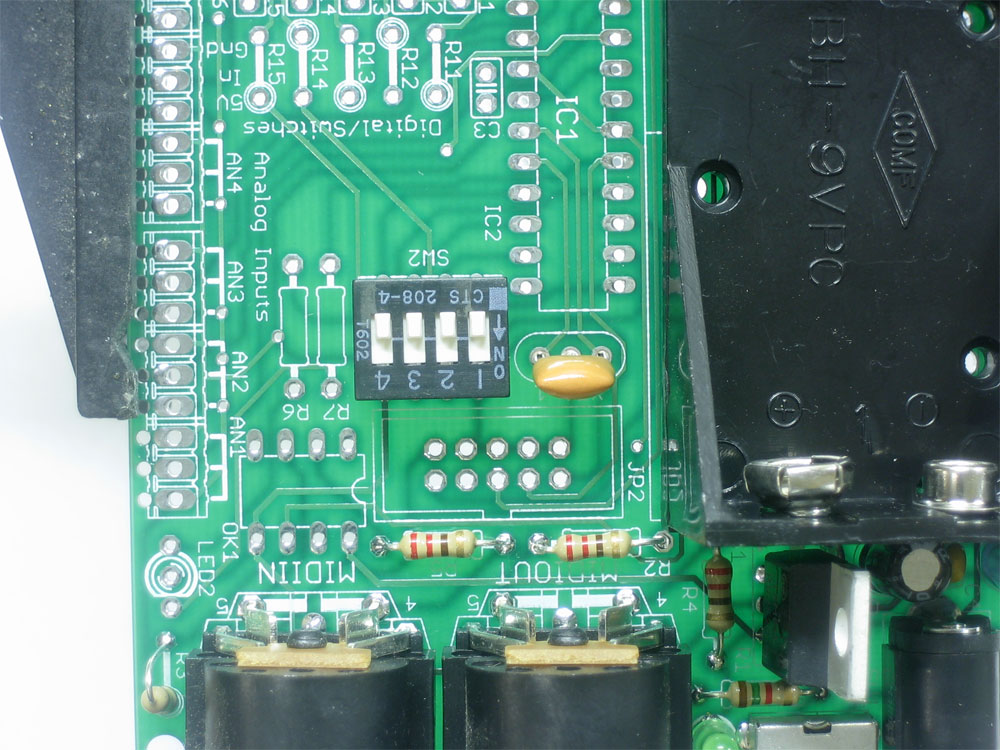
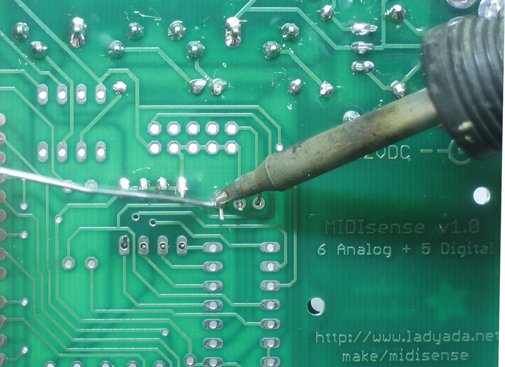
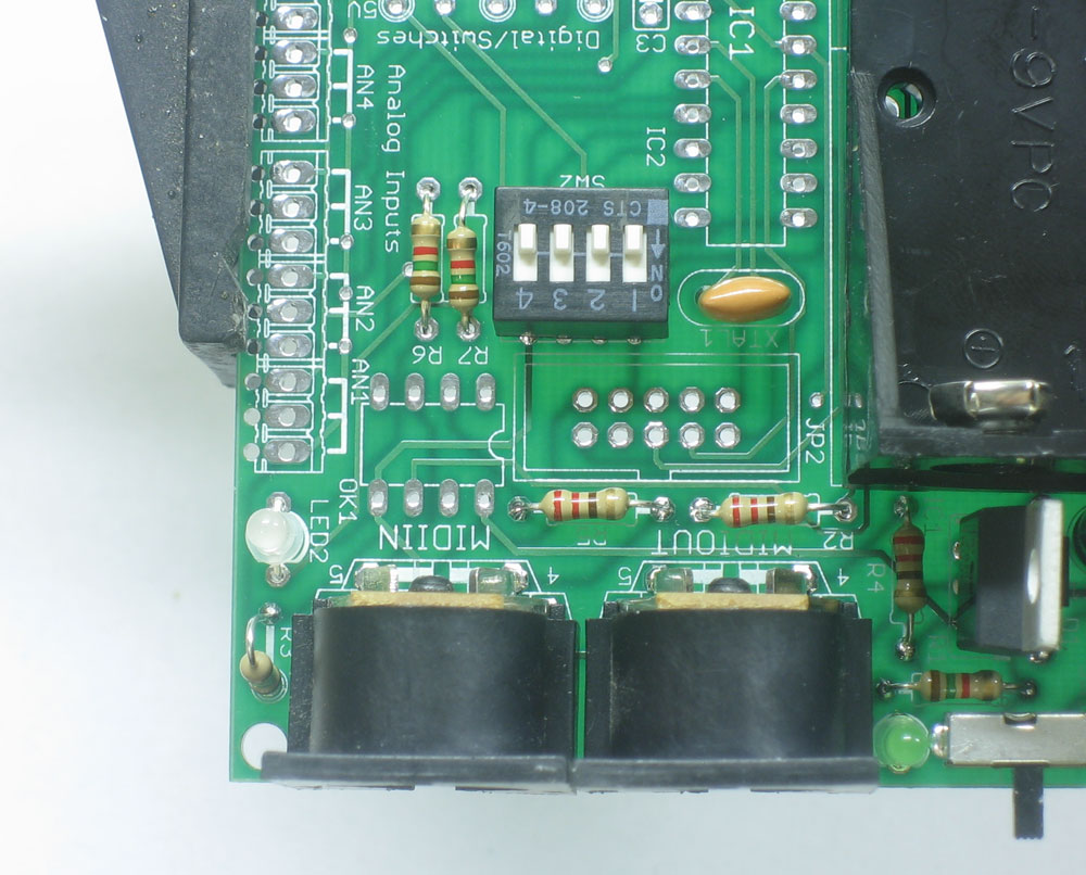
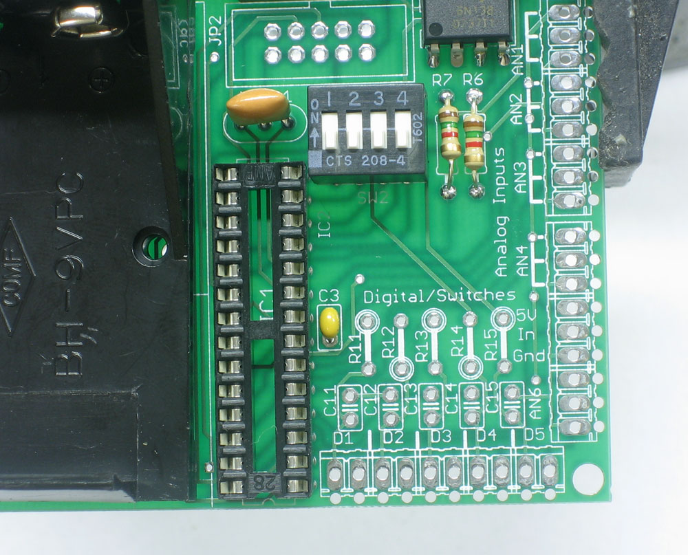
Next is the MIDI address selector (4-dip switch) SW1 and the 16MHz ceramic resonator XTL1 The DIP switch lets you set the inherent address of the MIDIsense (which, admittedly, isn't used as much now that it is software-selectable). The ceramic resonator is like a watch crystal, and allows the microcontroller to keep precise timing so that it can generate and read MIDI signals without error. Solder in the two parts, and clip the small leads from the oscillator. |
|
Next its time to place the MIDI-activity dual LED. This LED is lit up by the microcontroller when it receives or transmits MIDI data. Its very useful for debugging! The LED actually has 2 LEDs in it, one red and one green. The green one is lit when data is sent and red is lit when data is received. If you put the device in backwards it will be the opposite, so make sure its placed right. There are three legs, long medium and short. The long lead is in the middle, the medium length lead should be next to R3 (in the first picture, this is towards the bottom/south of the photo) Also place the two choke resistors for the LEDs, R6 and R7 Solder and clip |
|
Next is the optocoupler OK1. An optocoupler is used to isolate MIDI devices. Any MIDI input is put through the optocoupler, which basically converts the electrical signal to optical and back again, this means that there's no risk of shorts or ground loops in your MIDI setup! The optocoupler must go in the right way, you can see that in the top photo, the chip has a dot in one corner. The chip must be placed so that the dot is on the same side as the notch in the silkscreened photo underneath (to the left as shown here) Turn over the board and solder in the chip. |
|
Next is the socket for the microcontroller chip and the last ceramic capacitor C3. The microcontroller is socketed because theres a chance that it may need to be replaced or upgraded, so its better to not solder it directly to the PCB. To make inserting the microcontroller easier, you should make sure the socket is oriented correctly. Place it so that the notch at the end of the socket matches the notch in silkscreened image. In this picture, that would be at the bottom. |
|
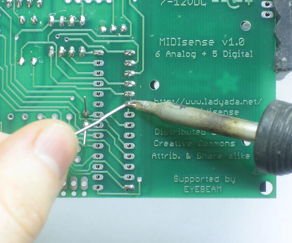
If you're planning on reprogramming the chip with a microcontroller programmer you can solder in the 10-pin in-circuit programming header. Make sure the notch is positioned correctly, at the bottom of this photo. If you're just planning to upgrade the MIDIsense firmware using the software bootloading capability, you dont need this. Its basically only useful if you're about to do some serious hacking. |
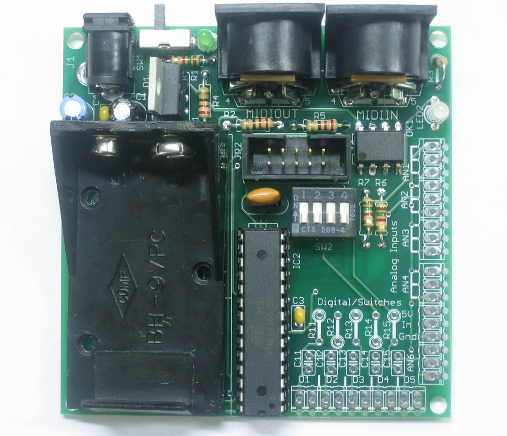 |
Place the microcontroller IC2 in the socket. gently flatten each side of the microcontroller pins against the table so that they are parallel and you can plug the chip in. Be careful when you insert the chip to make sure its in the right way (the notch at the bottom as shown in the photo) and that the pins arent bent or broken. |
|
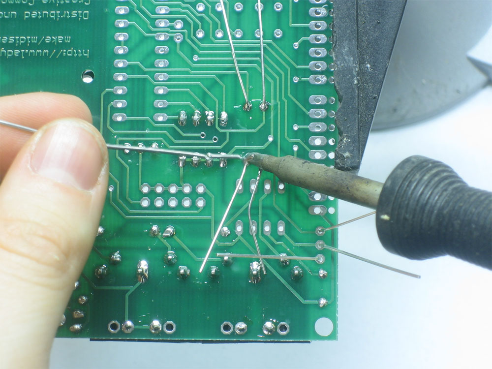
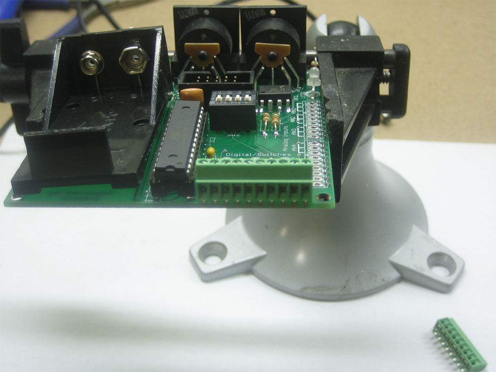
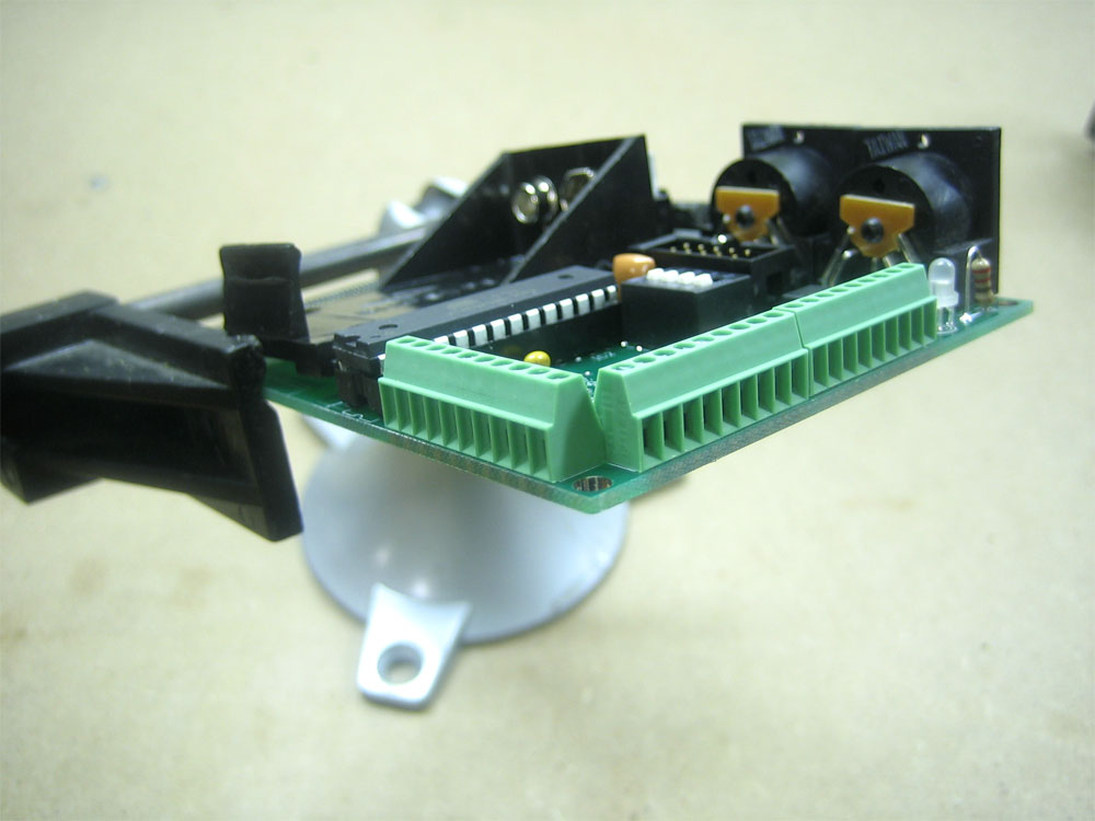
Place the three terminal blocks. One is 10-position, that goes on the bottom as shown here in the first photo. Make sure its placed as shown (not backwards), otherwise it will be very difficult to use. Then place the two 9-positon blocks. they shold also be soldered in so that the terminal openings face out. |
 |
You're done! Now go read the user manual... |