Some web browsers (IE, and others) do not like my website so much and load the photonotes slowlsy. And so, if you are wondering where the rest of the instructions are, either wait a while and IE will eventually display it (below here). Or download Firefox/Safari. It will work a lot better!
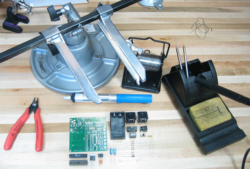 |
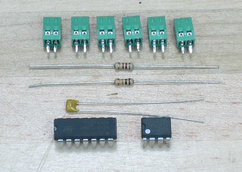
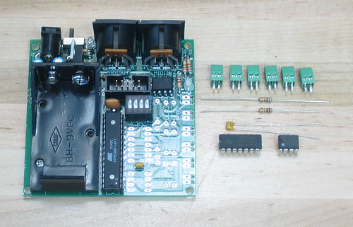
Get your workspace set up! |
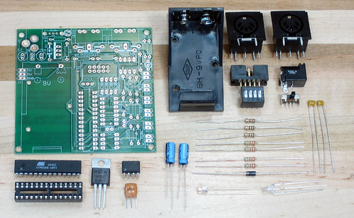 |
You dont have to arrange your parts up, but double check you have all of them |
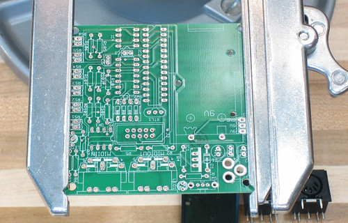 |
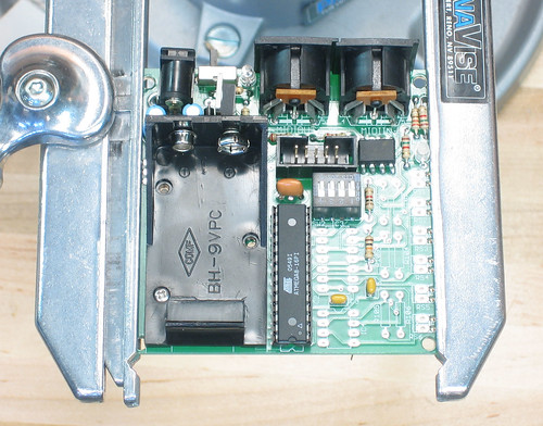
Place the circuit board in your vice/holder. |
|
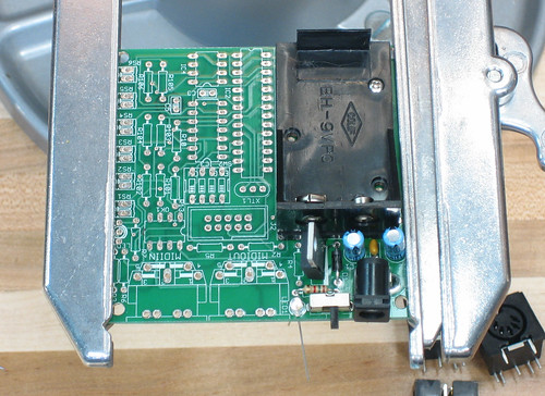
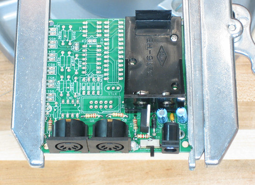
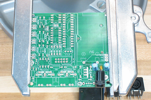
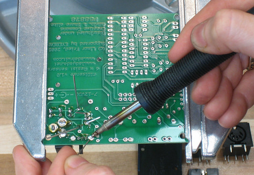
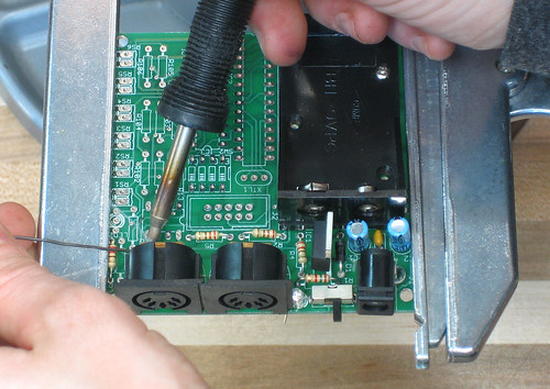
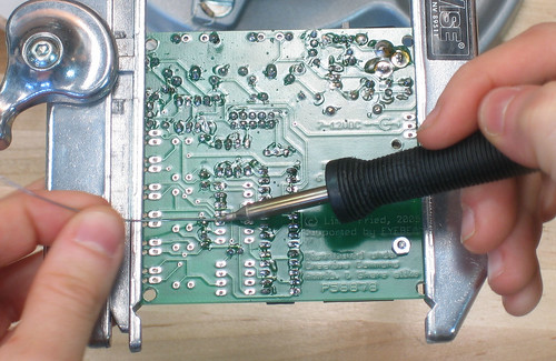
We'll start with the power supply, place the power jack, two blue capacitors and the little ceramic capacitor, as shown. Be careful to note that the the blue capacitors go in the right way. Bend the leads a little as you do so when you turn the board over, the parts dont slip out.
|
|
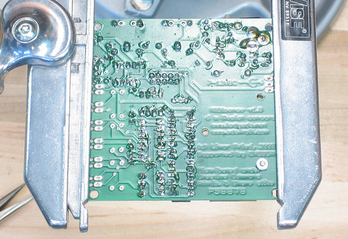
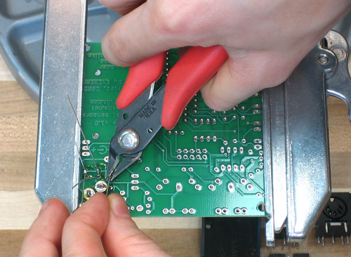
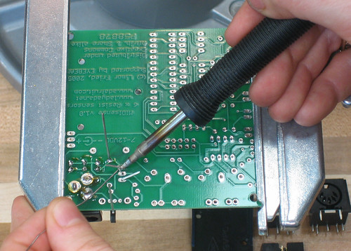
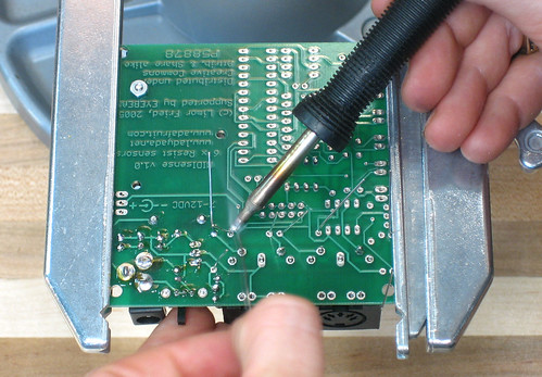
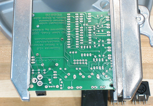
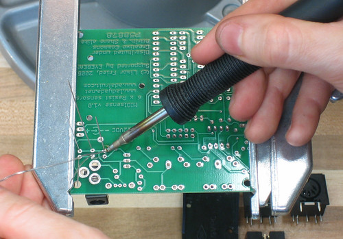
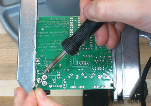
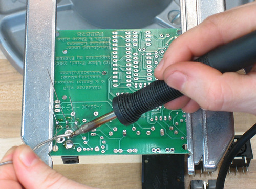
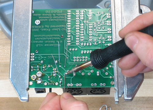
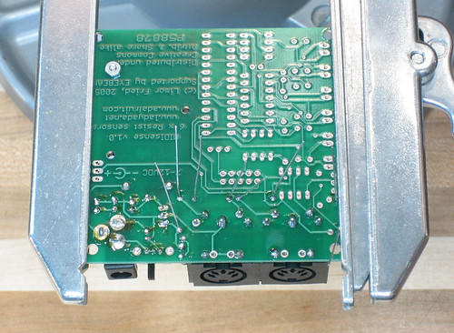
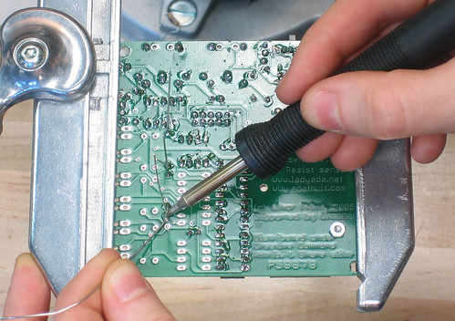
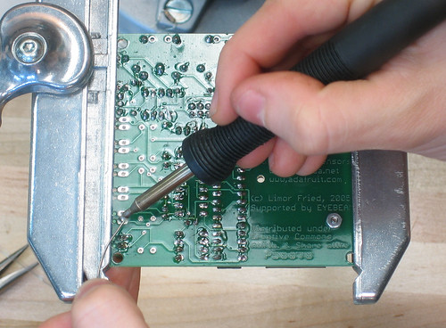
Then, turn the board upside down, and solder the parts in. Make sure that you put plenty of solder on the power jack, the solder provides a mechanical as well as electrical connection, so if you put too little it will break from the repeated stresses of plugging/unplugging |
|
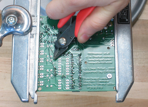
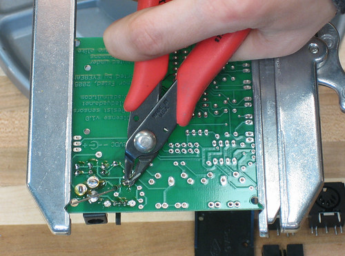
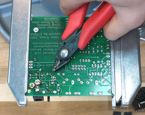
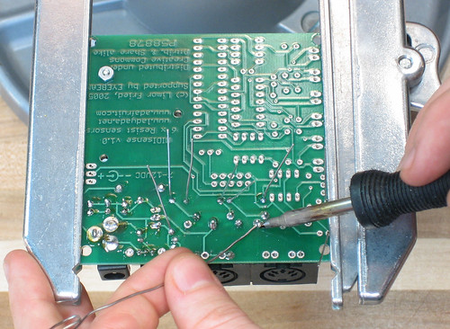
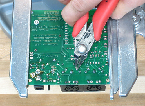
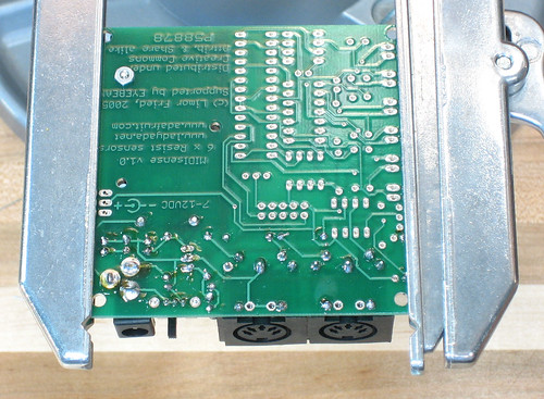
Now use the small diagonal cutters to trim the long leads. Dont cut too close to the board, or too far. The final solder joints should look like a Hershey's Kiss: blob on the bottom that comes up to a point and then no long tail. |
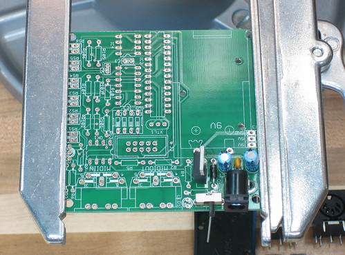 |
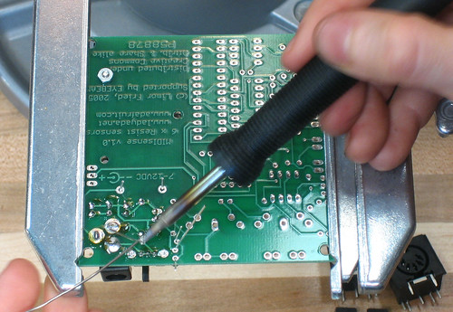
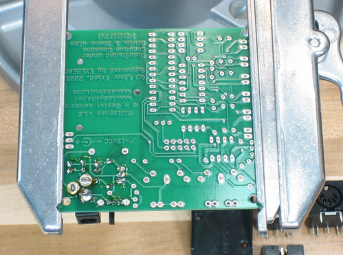
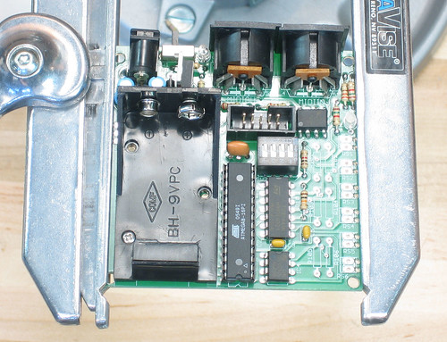
Now put in the diode, the switch and the 7805 voltage regulator. Make sure to line up the white stripe on the diode with the white stripe in the picture. Also line up the metal tab of the 7805 with the picture, it's the white stripe. |
|
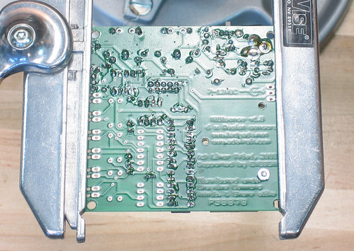
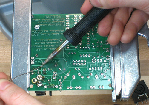
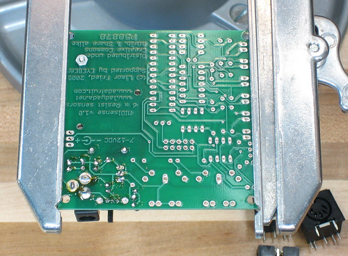
Turn the board over and solder/clip as before. |
 |
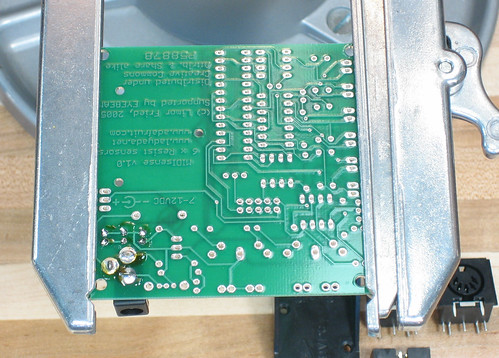
Finish off the power supply by inserting the battery holder, and attaching it to the board with the 4-40 screw and nut. Also, the LED and the LED resistor. The LED goes in only one way, there's a flat edge in the plastic case that matches the flat edge in the picture, so line those up. The resistor can go in either way. |
|
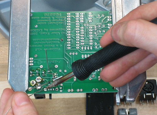
Solder the parts in. |
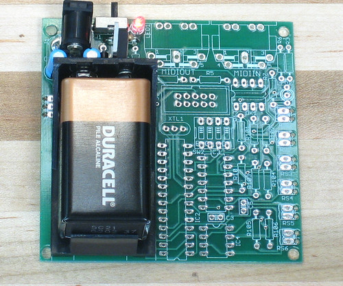 |
Now test the power supply. Insert a good 9V battery (or plug in a 7-12VDC positive tip wall adaptor into the jack) and flip the switch to the right. The LED should light up and nothing should start smoking :) If the LED doesnt light, check to see if the diode is in correctly (the white stripe should be on the side that's closest to the battery), the 7805 is in correctly and/or isn't extremely hot. Also make sure the LED is in right! |
|
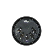
OK now its time to place the MIDI parts. Insert the 2 MIDI jacks and the four 220 ohm resistors as shown. Note: there was a PCB error in some very early MIDIsense resistive boards, R3 and R6 may be swapped! Check that the 220 ohm resistor connects to the MIDI jack and the ~1.5K resistor connects to the bi-color LED. To keep the MIDI jacks from falling out when you turn the board over, solder a pin or two from the top, to keep the jacks in place |
|
Solder Solder! Clip! OK! |
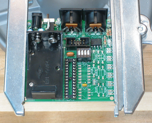 |
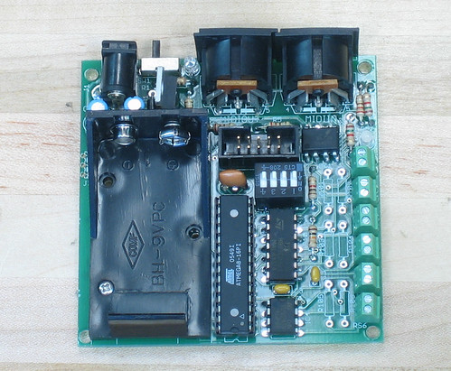
Place the remaining base parts: the programming header, MIDI Optocoupler, MIDI address switch, 8Mhz ceramic oscillator, 0.1uF capacitor, microcontroller socket, dual LED and two LED resistors. The programming header should be placed as shown, with the notch matching the picture. The optocoupler also goes in only one way, the little dot inscribed on the chip goes on the same side that has a notch out in the picture. The switch should go in as shown, although if it goes in backwards, it's fine, you'll just have to note that the numbers are backwards. The socket should go in so that the notch in the socket matches the one in the picture. The dual LED, like the powerindication LED has a flat side that matches the photo. If you put it in backwards, the colors will just be swapped. (As is, green means outgoing MIDI and red means in.) The capacitor, oscillator and resistors go in either way. |
 |
Solder in the parts. |
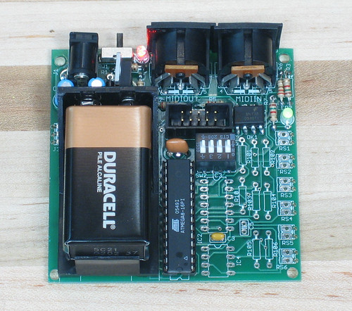 |
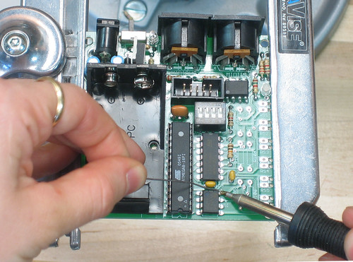
Insert the microcontroller into the socket, matching the white triangle/notch with that in the picture (and hopefully the socket). Plug in the battery/wall adaptor and turn on the device. After a few seconds the green LED should start flashing, indicating that MIDI is being sent out and that the microcontroller is working OK. |
|
Get all the parts necessary, as well as a MIDIsense board with the base part all done |
 |
Place C5, R10 and R13 |
|
Turn the board over, solder & clip |
|
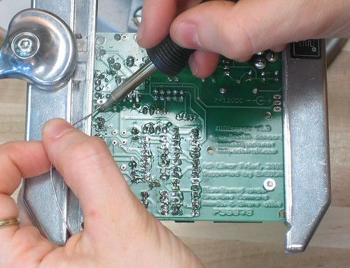
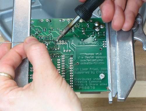
Place the two op-amps, with the notches on the chips matching the ones in the silkscreen. To keep them from falling out when you turn it over, try tacking two corners from the top. |
|
Turn over the board and solder the rest of the pins for the op amps |
|
To solder in the screw terminal blocks, dont turn over the board, they'll just slip out. Hold the block in with one finger while you solder from the other side, be careful not to burn your finger! The terminal blocks have two green pins that align with the mounting holes on the board so make sure the blocks are well seated before you solder them in. |
 |
OK you're done! |