Of course, the MIDIsense is designed to be interfaced with various sensors. Connecting sensors is very straightforward. There are lots of sensors documented on the Sensors pages, with tips and tricks for how to connect and configure them
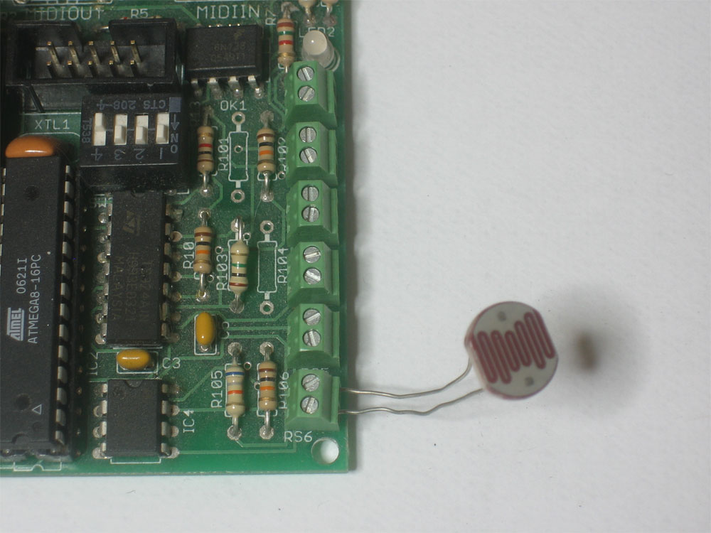
If you bought a resistive sensor board, it will come with a CdS cell (photo sensor) and a matching 10K (brown black orange gold) resistor. If you want to dive in and just get started using this sensor, you can use these in one of the sensor ports. In this image I used sensor #6, in which case the matching 10K resistor must go in R106
If you bought an Analog/Digital Input+Output board, your kit will come with a single mini-potentiometer. You can simply connect this up to one of the analog inputs, as shown

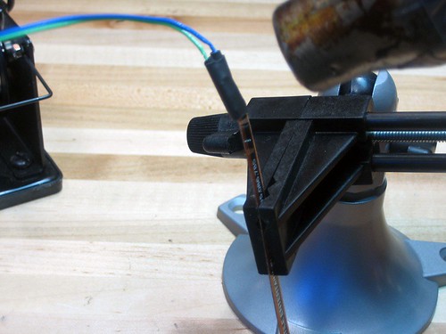
Before the sensor can be connected to the MIDIsense boards, it has to be prepped. Luckily, this is very simple. Just solder on some extention wires! Here is the defacto standard method, illustrated. For more hints/notes, mouse over the images.
|
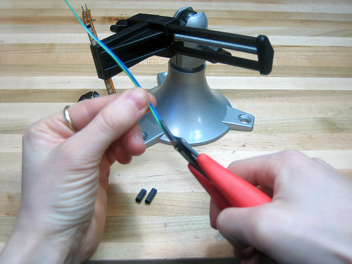
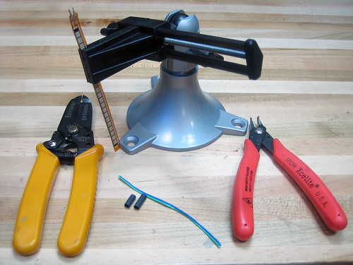
Get your bench set up for soldering. Shown: wire strippers, sensor, vice, ribbon cable, heat shrink, clippers. Not shown: Soldering iron, solder, heatgun/hairdryer. |
|
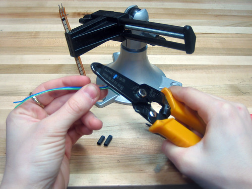
If you're using ribbon cable, split both ends about an inch. Then wirestrip the ends, about 1/4". |
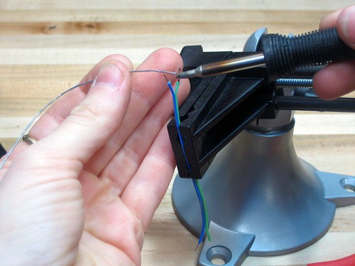 |
Tin both ends of both wires |
 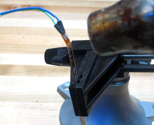 |
Slip the heatshrink on and THEN solder the sensor to the wires. Then shrink the heatshrink with a heatgun or hairdryer. |
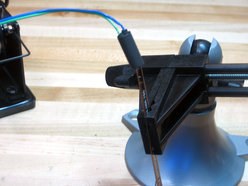  |
For extra credit, get a large piece of heatshrink and cover the two smaller pieces, this will make it even more durable! |
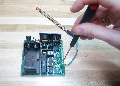 |
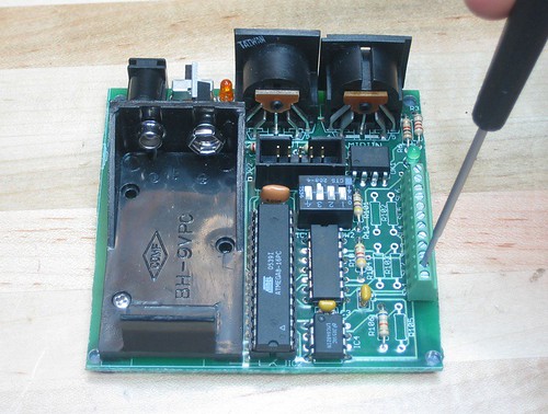
For the resistive sensor board, select the proper matching resistor from the sensor guides and solder it into the location corresponding with the screw terminals you're planning to use (see below).
Install the sensor by unscrewing the two terminals with a precision screwdriver (like for eyeglasses) Slip the wires in, and then retighten the screws. Ok you're done! |