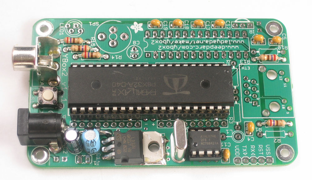
There are a lot of parts in the ybox2 kit but it is not a particularly difficult project to make. Double check each part before placing it and you will be able to finish this kit in about 2 hours.
Check all your parts against the bill of materials Get ready by placing the PCB in a vise Heat up your soldering iron to 700deg F, clean the tip and make sure your sponge is wet Lets go! |
|
 |
We'll begin with the first component, the power connection jack. Place the jack as shown, make sure it is 'snapped in' and is sitting flat on the PCB |
 |
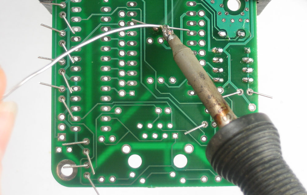
Turn over the PCB. Holding the soldering iron with your dominant hand, press the hot tip against one of three pads (the silver rings) and the lead (the metal leg that sticks through the ring) as shown. After 1 or 2 counts, poke the end of the solder roll into the heated pad/lead so that it melts and fills the pad. then wait another count to make sure the solder has flowed completely, and remove the soldering iron. |
 |
Repeat for all three pads. The solder should be shiny, smooth and completely fill the holes. |
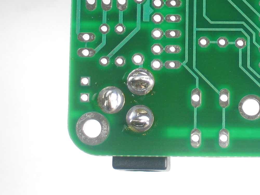 |
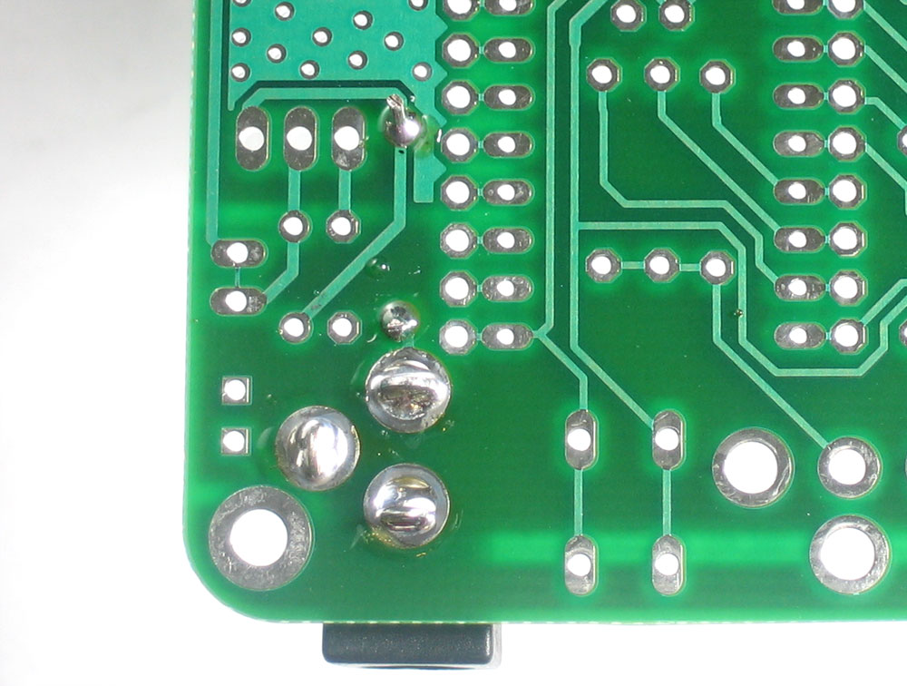
Check that your solder joints look good and strong as on the left. You can always resolder it! The solder joints on the jack are not just electrical, they are mechanical as well and keep the jack from breaking off when you plug in power. |
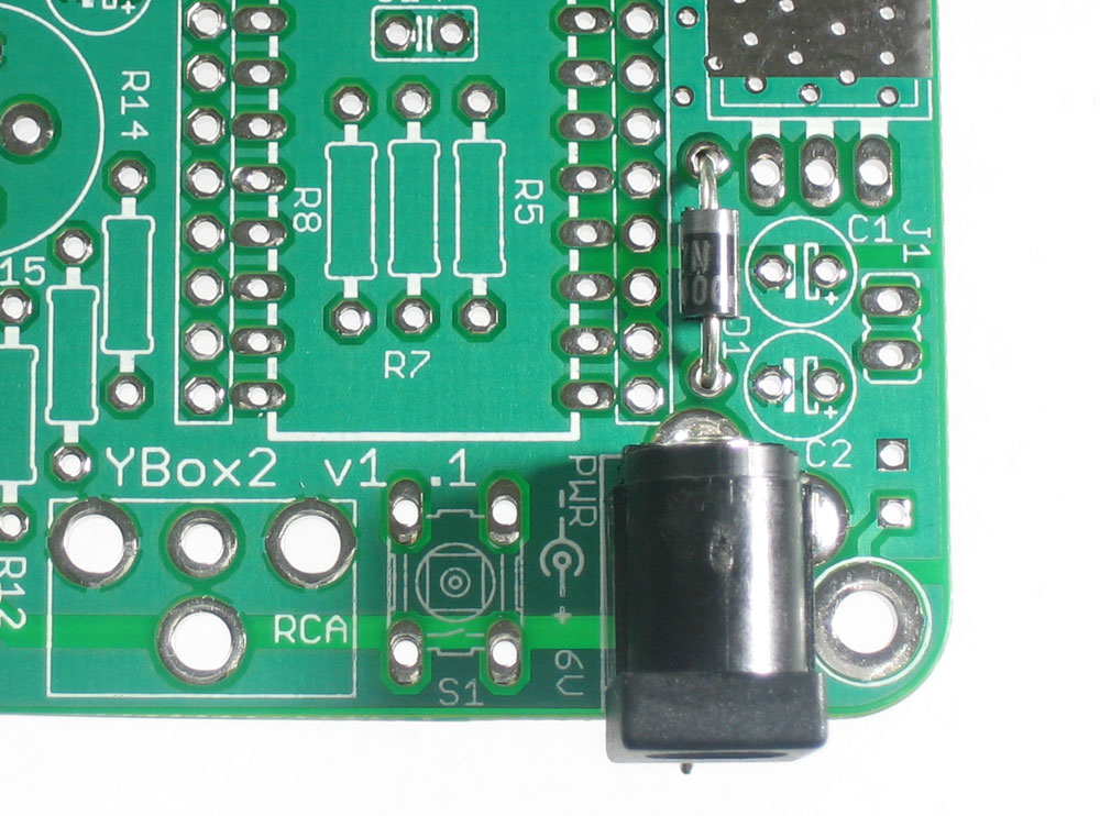 |
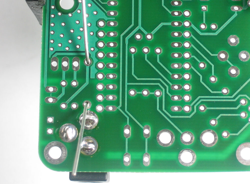
Next is the 1N4001 diode D1 . A diode is a semiconductor that only conducts electricty in one direction. In this case, the diode is used to protect the ybox2 from plugging in an incorrect power supply. Diodes must be installed correctly or they will not work (since they are unidirectional) Make sure the silver stripe on the end of the diode's body matches the white stripe on the PCB silkscreen. Fold the diode into a 'staple' shape and place it. Make sure it sits flat against the PCB |
 |
Bend the legs of the diode so that when the PCB is flipped over it will not fall out. |
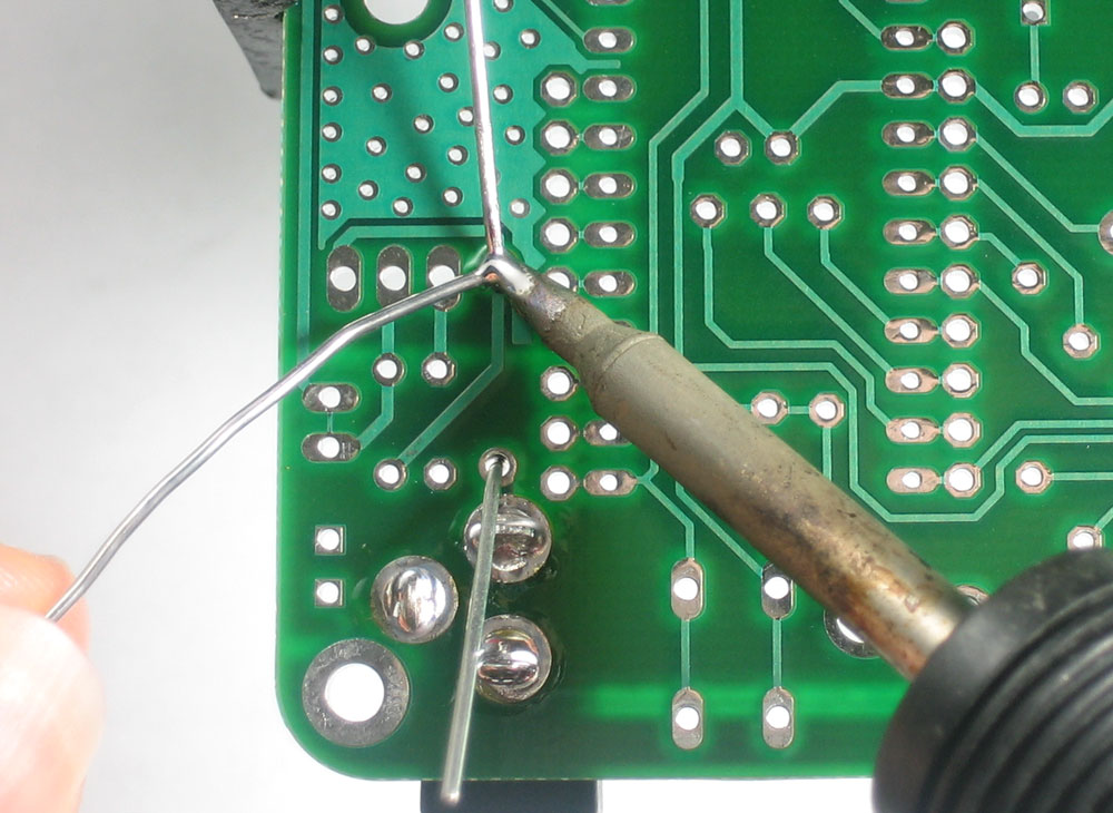 |
Just as you did with the power jack, solder each pad and lead. |
|
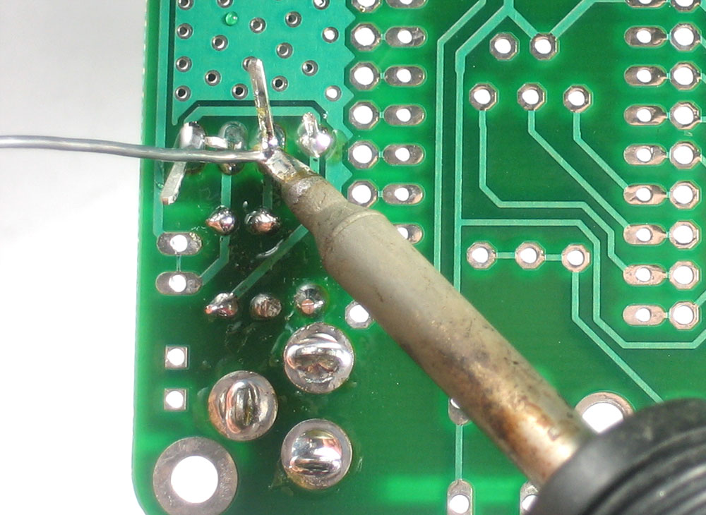
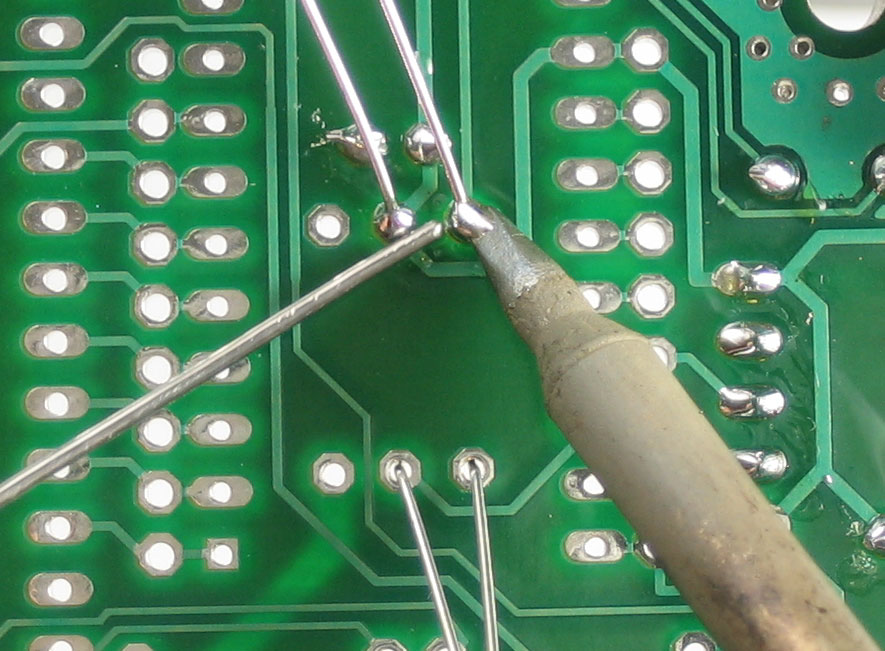
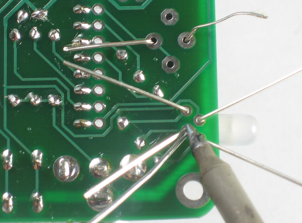
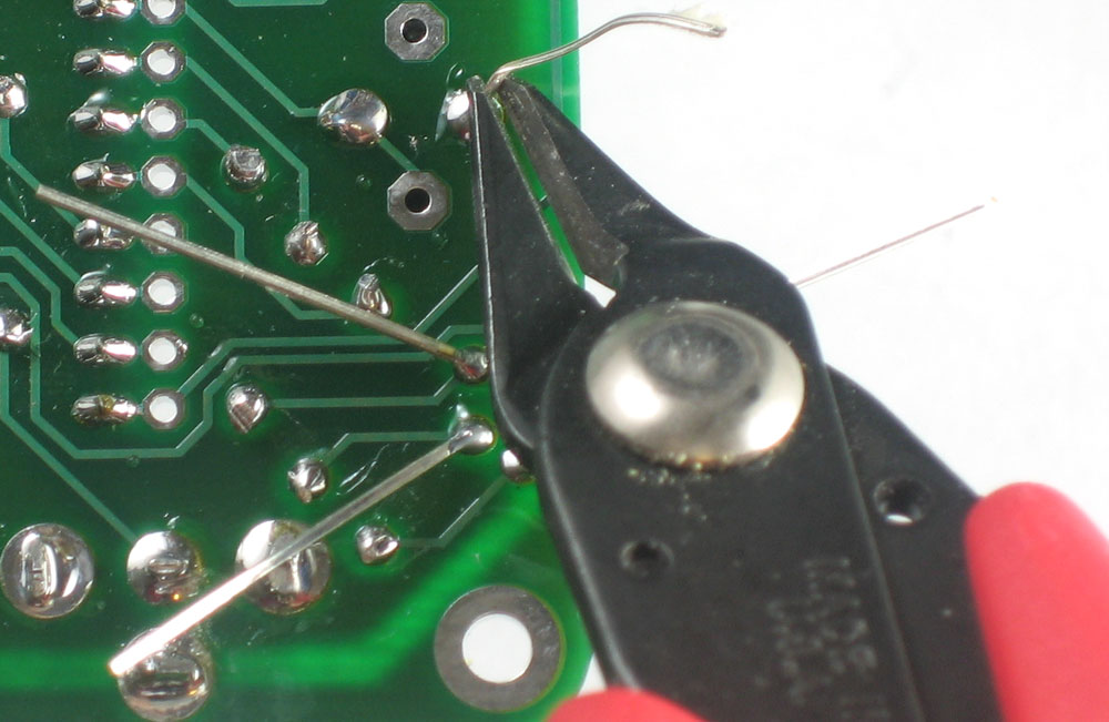
When you're done soldering, the long leads must be clipped off. Use the diagonal cutters to clip the leads right above the solder joint. Make sure you dont clip so close you destroy the solder joint, but not so far either, that there is a long lead - that can cause problems if it shorts against another part. See the images to the left. |
|
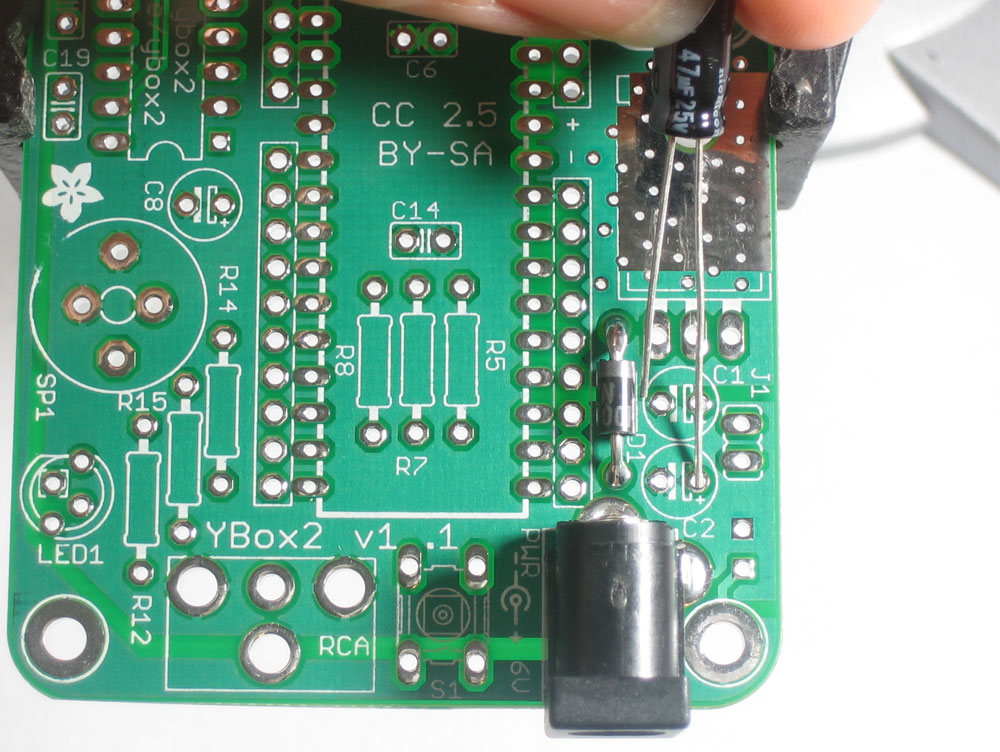
Next is the 47uF, 25V capacitor (this is different than the two 100uF, 10V capacitors) C2. Electrolytic (can-shaped) capacitors are polarized and must be placed in a certin orientation or they can pop! Check the capacitor, there is one leg that is longer than the other, this is the positive lead. Make sure the positive lead goes in the pad marked with a small + sign. In this image, thats the right-hand pad. |
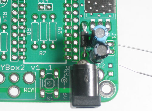 |
Next, place the 100uF capacitor C1, check polarity again to make sure you've got them in right. There should be a stripe on the left side of each capacitor (the negative side) |
 |
Solder in both capacitors. |
 |
Clip the long leads with the diagonal cutters. |
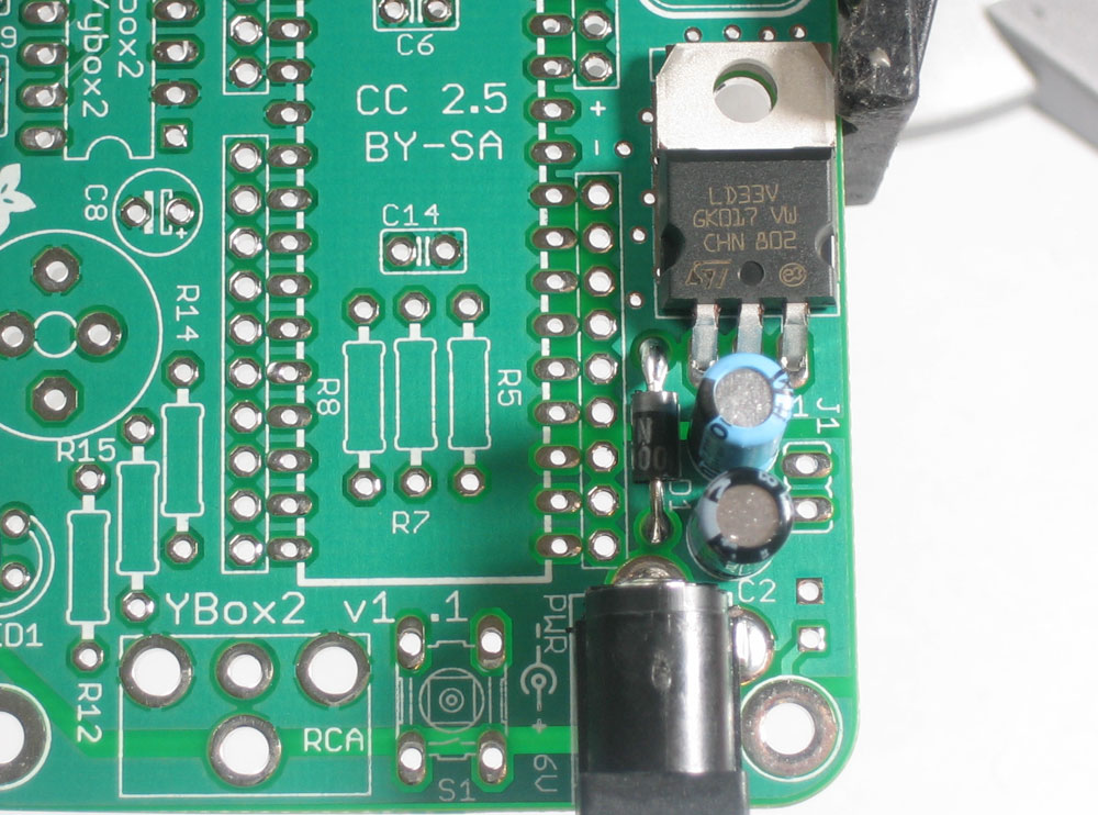 |
Next is the LD33V chip, which is the 3.3V regulator. This is the device that takes the 9V input from the power plug and converts it down to 3.3V that the Propeller chip wants to run at. Bend the legs before inserting the part so that the hole in the heatsink tab matches the hole in the PCB. |
|
Solder and clip the three leads. |
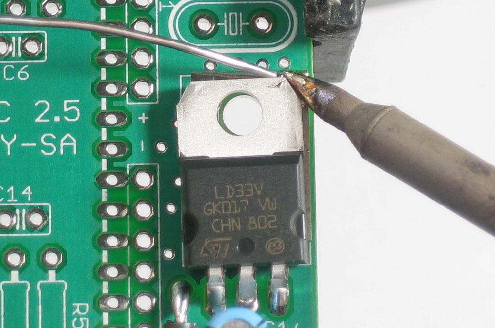 |
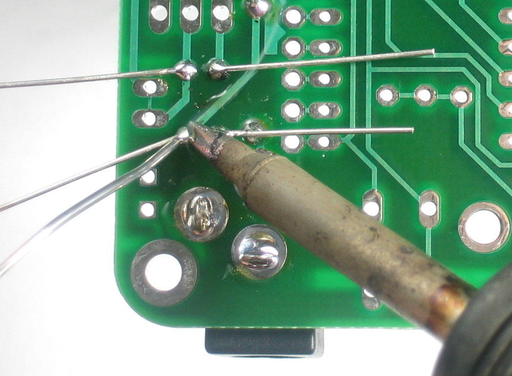
Because the Propeller is a very fast chip (8 cores running at 80MHz!), it requires a lot of power from the power supply regulator. That is why the regulator chip has a heatsink tab. We will solder the tab to the PCB which will act as a heat sink. Using your soldering iron, heat up a corner of the tab and the huge silver heatsink-area underneath. It will take a few seconds to get it hot enough so that you can solder the heatsink to the PCB (since, its a heatsink) Poke a small bit of solder in (to 'tack it in place') |
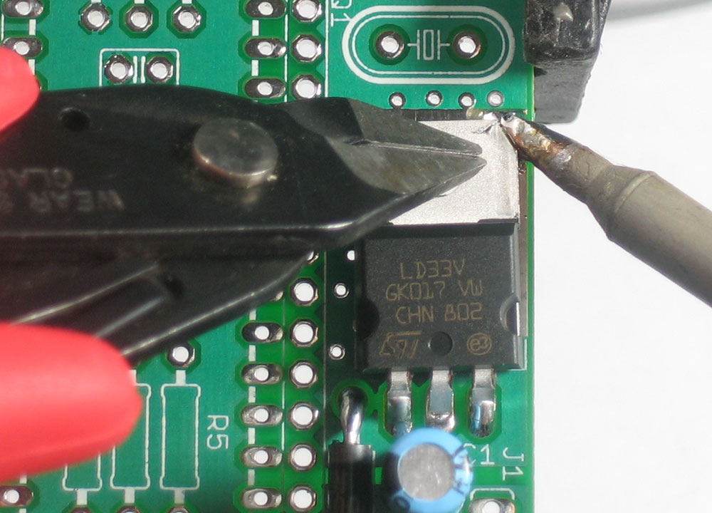 |
Once you have a small corner tacked, put down the solder and using your other hand, press down on the tab so that it will sit as flat as possible, and reheat that corner until the solder wicks to the tab. Again, this will take a few seconds. |
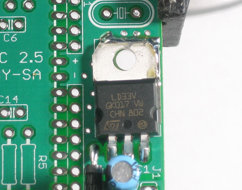 |
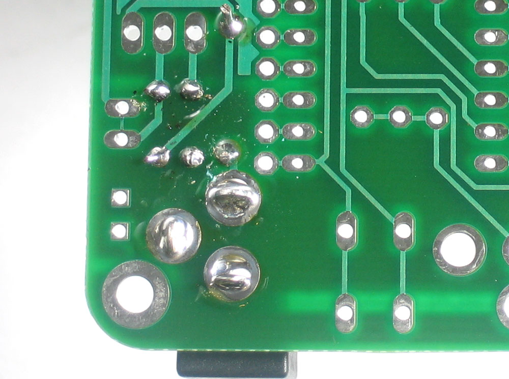
Add more solder so that you get as much of the heatsink tab soldered to the pad. |
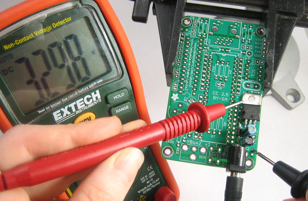 |
Now is a good time to check your handiwork. Put away the soldering iron and make sure the PCB is not in a metal holder that could possible short sections (this vise is made of plastic) Plug in the YBox2 kit to a 4.5V-9V DC power supply and using your multimeter, measure the voltage as shown (you can click on the picture for a higher-res version) |
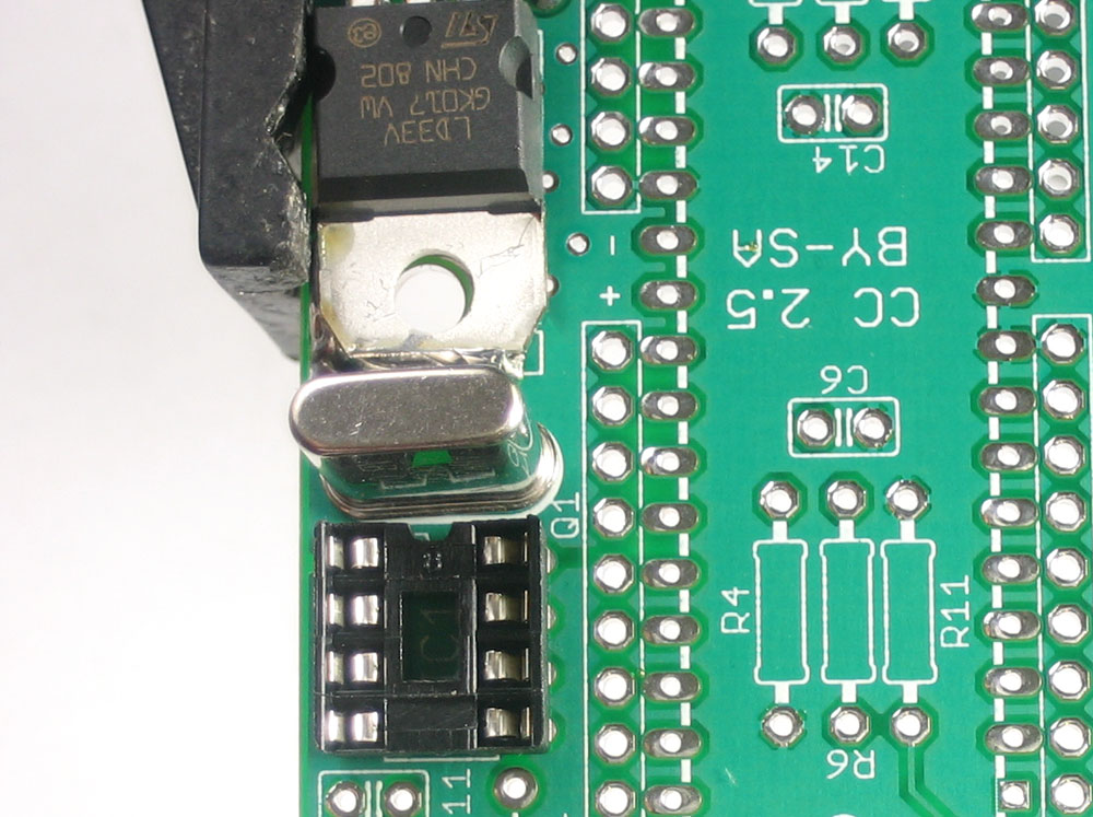 |
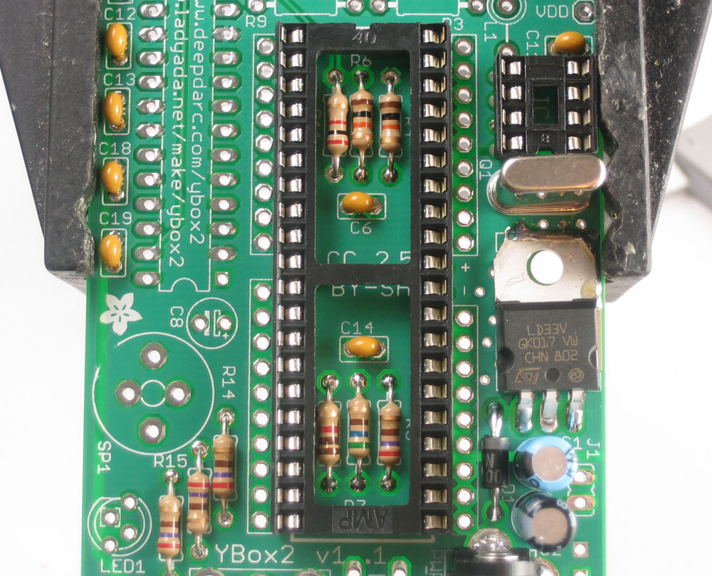
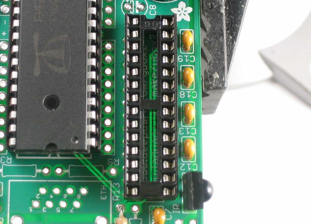
Next up are the 5.000MHz crystal and the 8-pin socket. The crystal provides the perfect timing needed by the Propeller chip to generate color video. (Technically, there is a different, much faster timer inside the Propeller that can go up to 80MHz. That timer uses the 5.000MHz crystal as a precision reference). The crystal can go in either way. The 8-pin socket will hold the EEPROM that stores our custom Propeller programs. The socket has a little notch in one end, which should match up with the notch in the silkscreened image (in this picture, it is north) |
 |
Solder the two legs of the crystal and all 8 legs of the socket. You'll need to clip the crystal but the socket legs are already short so they dont need to be clipped. |
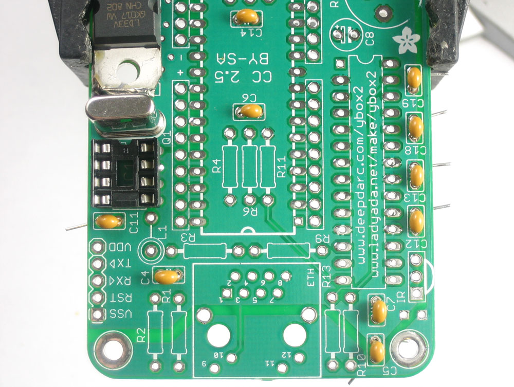 |
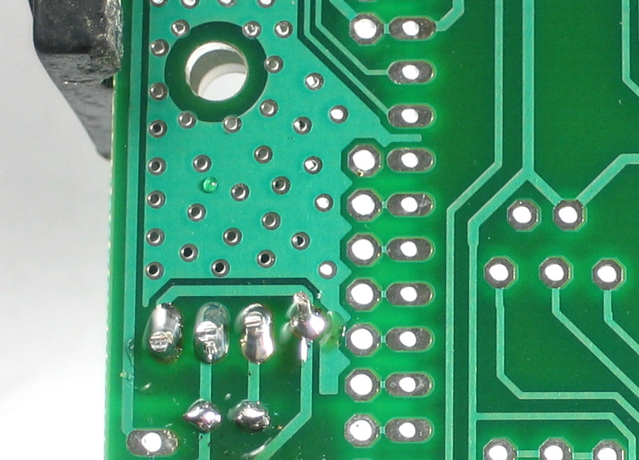
Next we're going to do all 10 ceramic 0.1uF capacitors: C4 C5 C6 C7 C11 C12 C13 C14 C18 C19. These are 'bypass capacitors', used to reduce high-frequency noise in the system. Since this project has many high-frequency components, it uses a lot of bypass capacitors! Ceramic capacitors, unlikle electrolytic capacitors, are non-polarized. That means they can be put in either way. |
|
Solder in all 10 capacitors, and clip the leads. |
|
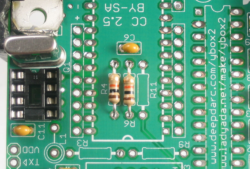
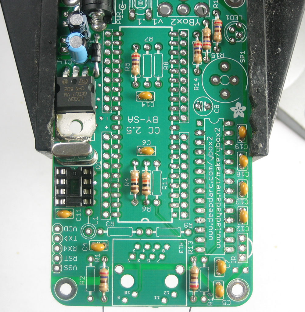
Next we're going to do the resistors. We'll start with the two 10Kohm resistors R4 and R6. These are both pull-up resistors, and are used to keep the data input pin and reset pin of the EEPROM and Propeller (respectively) at a high voltage during power-up so that they don't act oddly while the system is booting. These resistors have Brown-Black-Orange-Gold stripes on them, and are non-polarized. |
|
Next are the 6 270 ohm resistors R1 R5 R12 R13 R14 and R15 . The color stripes are Red-Violet-Brown-Gold. R1 and R13 are resistors that set the brightness of the Ethernet jack LEDs. R14 R15 and R12 , likewise, are used to set the brightness of the tricolor status LED. R5 is used for part of the video-generation circuitry. Solder and clip all of the resistors. |
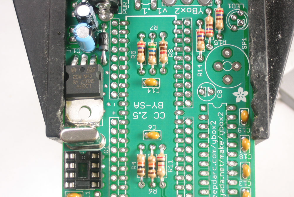 |
Next are some more resistors R11 (2.32K, in this photo we show a 2.0K resistor but your kit may have a slightly different value) used by the Ethernet circuitry to set how powerful the signal is. R7 (560 ohm Green-Blue-Brown-Gold) and R8 (1.1Kohm Brown Brown Red Gold) which complete the video generation circuitry. We will finish the remaining resistors later. |
|
Next we can place the big 40 pin socket that will hold the propeller chip. It should sit flat against the PCB, and the resistors should be 'out of the way' Just like the 8-pin socket, make sure the notch in the socket matches the notch in the silkscreen. Solder in all 40 pins |
|
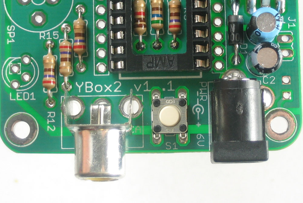
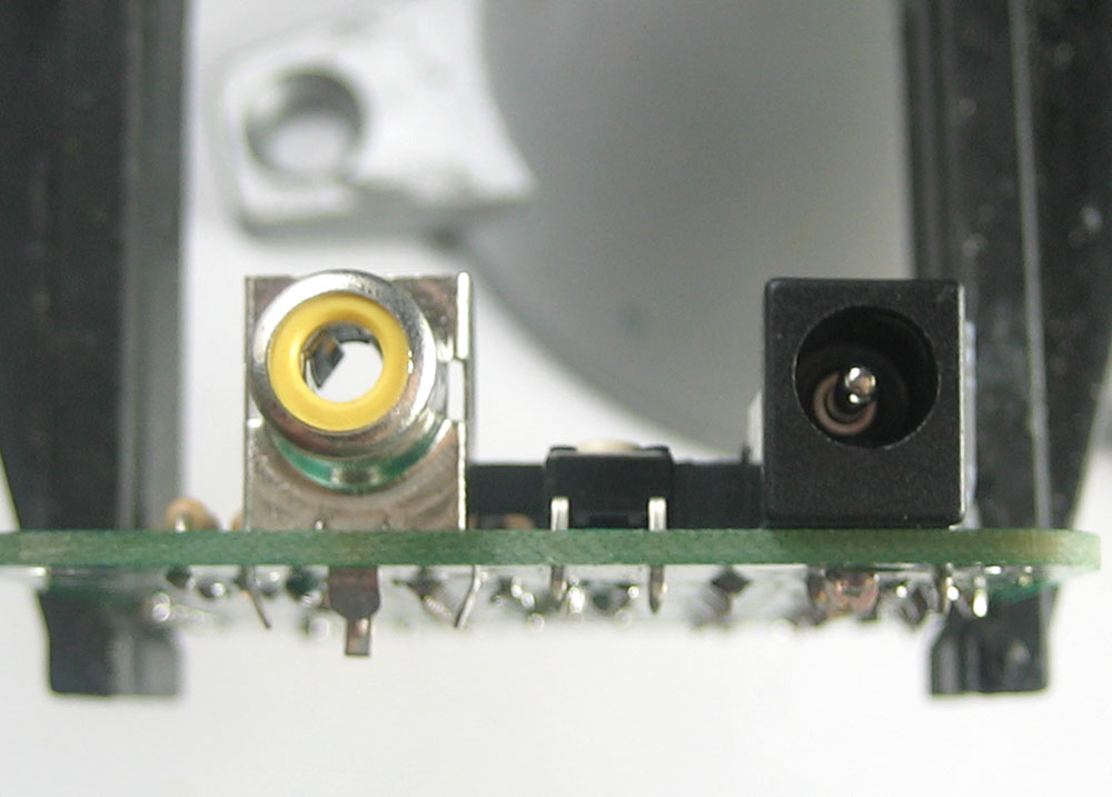
Next is the RCA jack (for connecting to a TV or projector) and the pushbutton S1. The RCA jack and button should snap in and sit flat against the PCB. The button is symmetric so it can go in 'either way' |
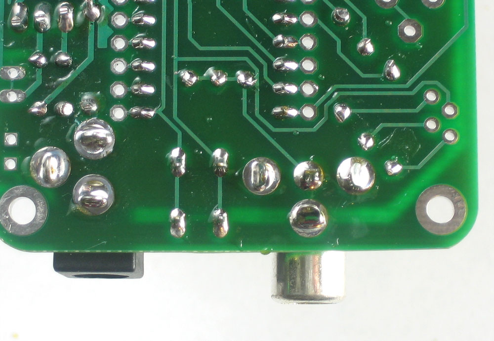 |
The RCA jack, like the power jack, requires a lot of solder so that it will have mechanical strength |
|
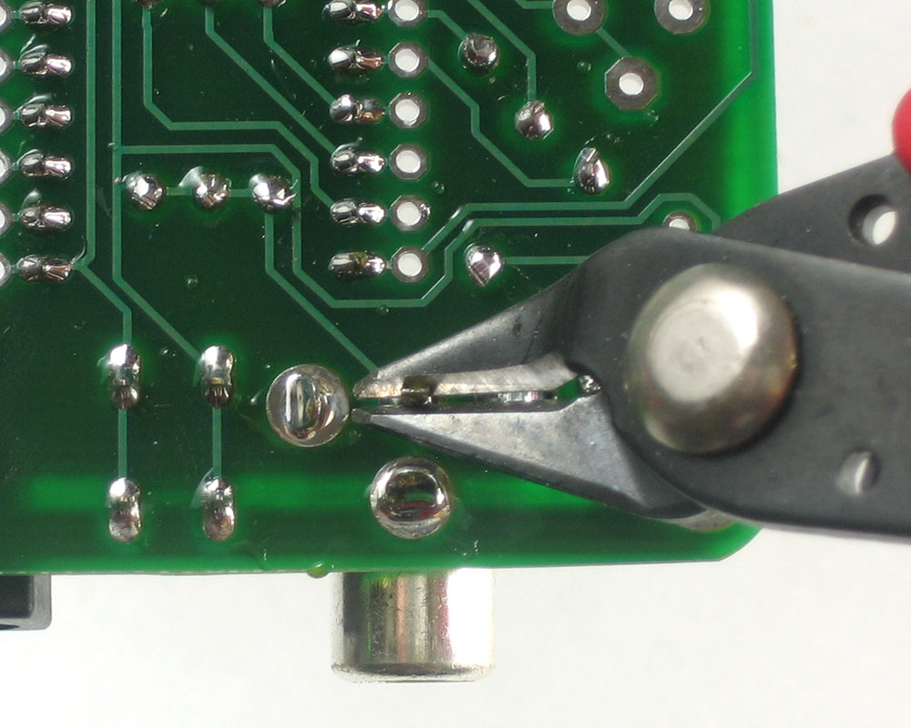
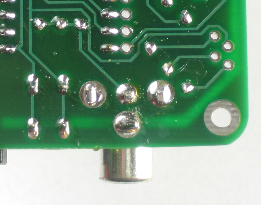
The RCA jack's leads are a little long so you may want to clip them. |
|
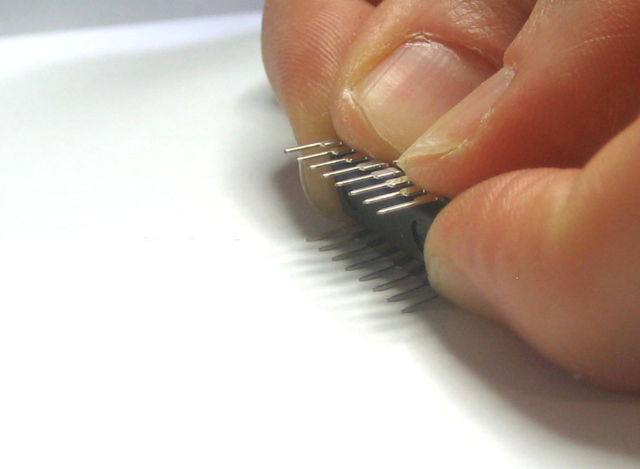
Next you can insert the Propeller chip and the EEPROM. Chips must be placed in the correct orientation or they can be damaged. Make sure the notches in the chips match the notches in the socket (which should match the silkscreen). Refer to the image to double check. To insert the chips, you'll need to bend the legs of the chips in a bit. You can grip the chip and bend the legs nicely against a table or something. Carefully rock the legs inwards until it is easy to pop the chips in. |
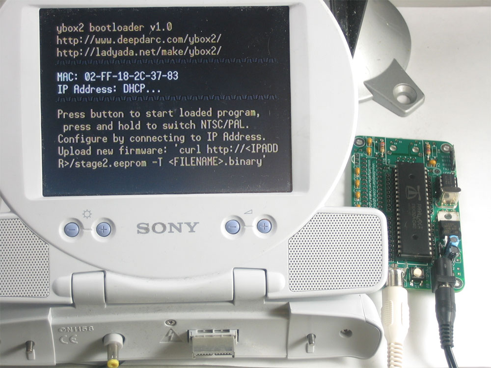 |
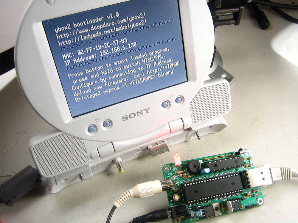
Now is a good time for another test. Remove the YBox2 from the vise, and plug in both power and a TV display. You should get the bootloader screen which will look something like the one on the left. You wont get a DHCP address because we haven't connected Ethernet. By default the YBox is designed for NTSC (USA, Canada, Japan, etc) If you have a PAL system (Europe, Australia, etc) you can switch modes by pressing and holding the pushbutton. After a few seconds it will switch over. |
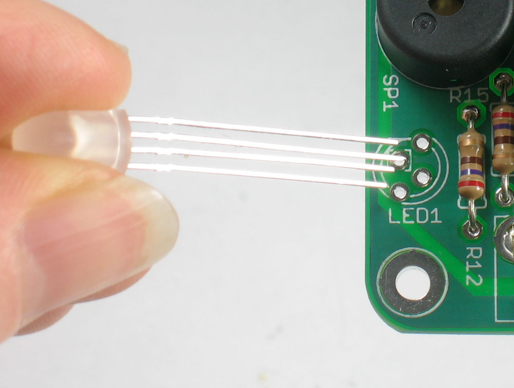 |
We'll do the buzzer and the tricolor LED next. The tricolor LED must go in a certain way or it will not light up (its made of light-emitting-diodes which are directional). Check the LED and find the longest lead, then make sure that lead goes into the pad that is marked with a square. Theres also a flattened side of the LED, and that matches up with the flat side in the silkscreened image. Make sure the LED has a bit of clearance so that it can be bent over later, perhaps 5mm above the PCB. |
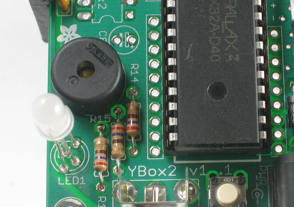 |
Next place the buzzer. Buzzers are non-polarized so it can go in either way. |
|
Solder all 4 leads of the LED and the two buzzer leads. Then clip them. |
 |
Next is the IR receiver (for using a 38Khz remote control) and the 28 pin socket. Make sure the IR receiver is pointing out as shown, and match the notches on the 28-pin socket Note: although not done in this photo, try to solder the IR receiver about 3mm higher than it would 'naturally sit' |
|
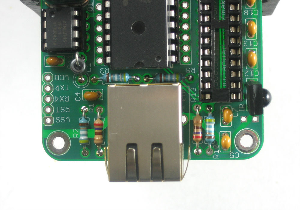
Next is all the stuff for the Ethernet subsystem. This includes the 4 blue 49.9 (yellow white white gold brown) resistors R2 R3 R9 and R10. These are used as 'balancing' resistors which make sure that the high-speed Ethernet cable is properly terminated. Also, place the metallic ferrite bead L1 (which is symmetric but does have a 'suggested orientation' on the silkscreen). The ferrite bead is used to keep high frequency noise from the board from leaking into the Ethernet cable. Finally, place the Ethernet jack, the jack has integrated LEDs and magnetics |
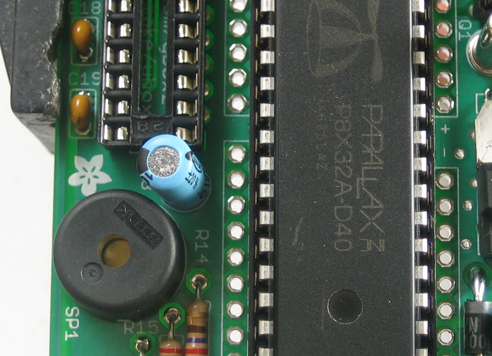 |
There is one more 100uF capacitor C8 that goes next to the buzzer, this is used as a bypass capacitor just for the Ethernet connection. Make sure you have the polarity correct and solder it in. |
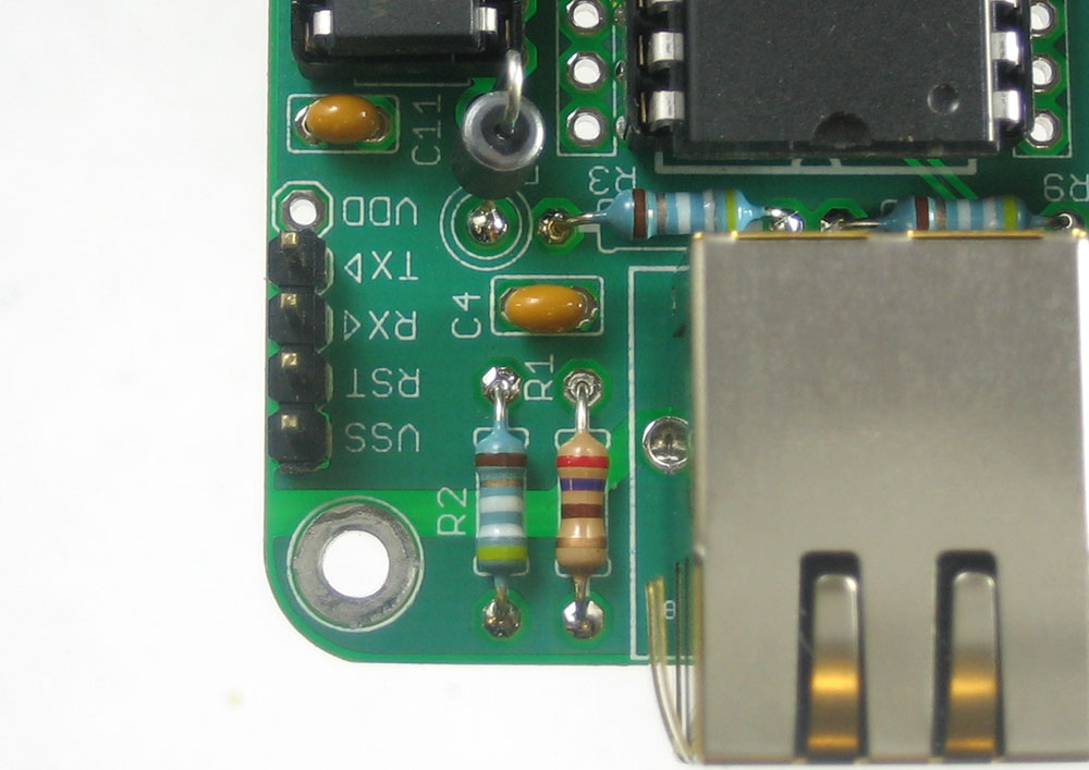 |
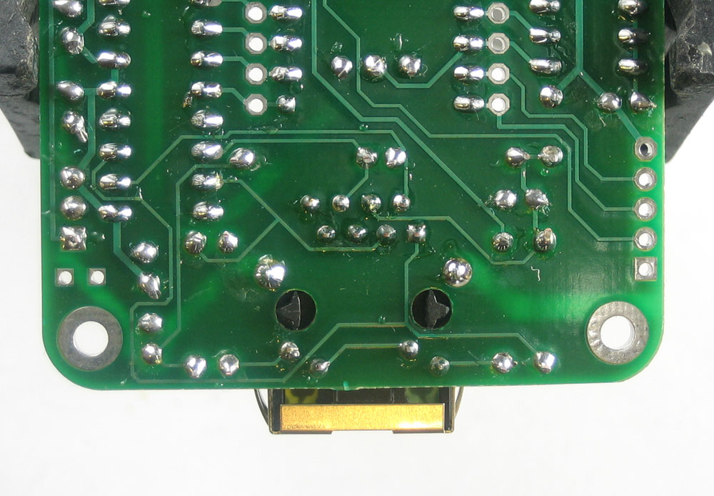
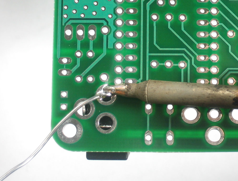
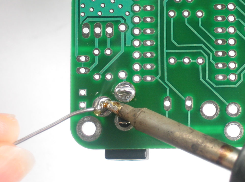
If you're planning to use a programming cable (such as a hacked FTDI cable, or a prop plug, you will want to solder in a 4-pin header. Make sure to not solder a header pin into the VDD hole. Its there for hacks and mods, and should not be connected to the programmer. |
| You are done soldering! | |
 |
Time for one last test before its time to case it. Plug in an Ethernet connection, a power supply and the RCA cable. The LED should light up and pulse, the buzzer should beep and you should be able to get an IP address from the DHCP server. Once you've verified you have a working system, you can continue onto the case. |