Once you've tested your GPS, its time to add the Arduino back in and show how to read and parse data. This step will verify you have both parts working togther.
Remove the shield and take out the jumper in the chip socket. Re-place the Arduino chip, making sure that no pins get bent and that the notch in the chip matches the notch in the socket. Put the shield back on and re-wire it so that the jumpers now look like this:
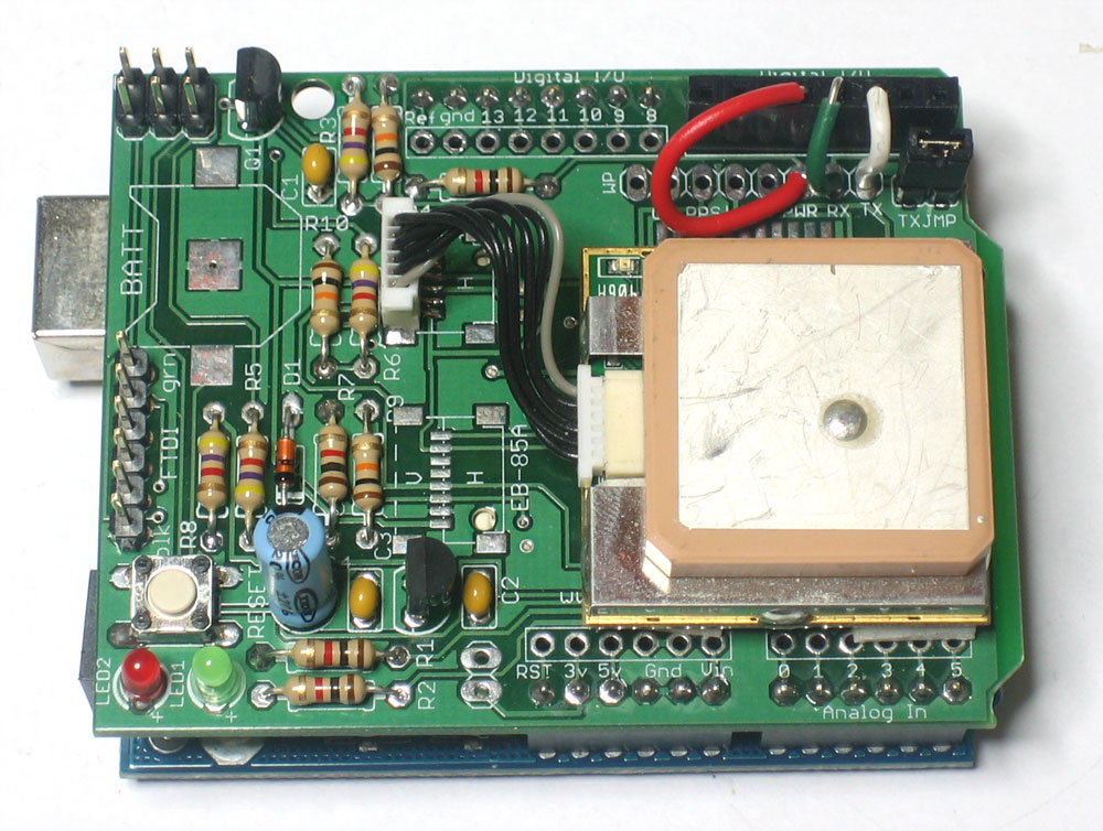
TX should connect to pin 2, RX connects to pin 3 and PWR connects to pin 4.
We're going to use software serial to communcate with the GPS. If you have an NG with a ATmega8 chip, you can use the SoftwareSerial library.
If you have an ATmega168 or 328, download and install the NewSoftSerial library from the download page. Install the library as necessary for your IDE
Download the GPStest_RMC sketch from the download page and upload it to the Arduino.
This time, when the GPS module gets a fix, it will parse out the data and display it in slightly more useful format. If you're planning to make locative projects that don't log to the SD card you can stop now. This sketch can provide the backbone of most locative art projects!