Here is a short technical description of how to chose the matching resistor for a sensor for the resistive sensor board.
Each sensor is hooked up in an inverting amplifier configuration.
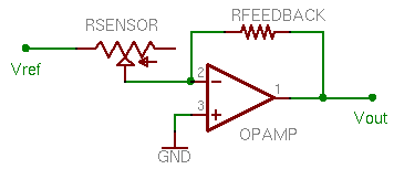
The sensor here is modeled as a variable resistor Rsensor, and the matching resistor is called Rfeedback. According to Op-Amp math, Vout = Vref * Rfeedback/Rsensor. By default, Vref is .5V and Vout can be as high as 5V-Vref so 4.5V. Lets say we want to select the matching resistor for the Bend/Flex sensor. So, we want to get the most range, so when the sensor is at its 'lowest' resistance, make Vout be maximized. Lets try Vout = 4.5V = .5V * Rf / 8K. That means Rf = 72Kohm. When the sensor is at its 'highest' resistance, 40K, Vout = .5V * 72,000 / 40,000 = 0.9V which is not bad, as you couldnt make it less than Vref (.5V).
In general I've picked out the best choice resistor, plus or minus a bit is fine.
The following sensors work best in the analog input port of an Analog/Digital I/O Board.
(show schem here)
The following sensors work best in the digital input port of an Analog/Digital I/O Board.
(show schem here)