You
are here
Testing
The only thing that can really be tested is the gating circuit.
Make sure the microcontroller is not in place while you do this test, otherwise you can destroy it! (This would happen if you built the whole thing and are testing this section now)
- Power up the main board by connecting J4 as before.
- Clip one end of an alligator clip to the south side of R146 (gate).
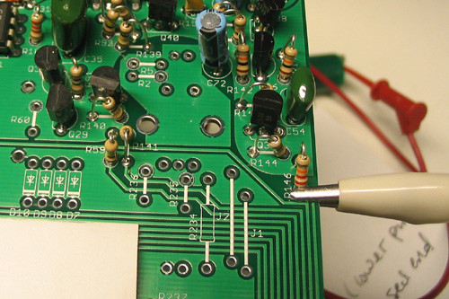
- Connect the other end to the exposed side of R3 on the IO board
(which provides +5V)
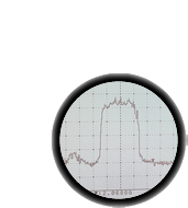
- Check the voltage at the north side of where D35 goes, using a scope or meter. When the clip is connected, there
should be 12V. When its not connected, there should be 0V.
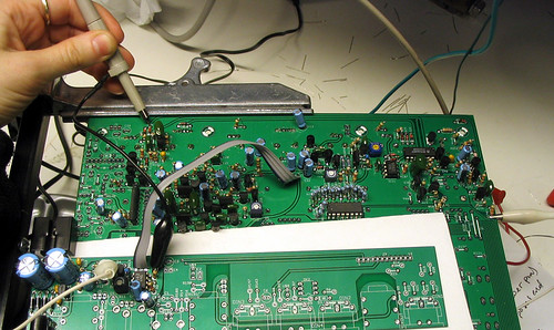
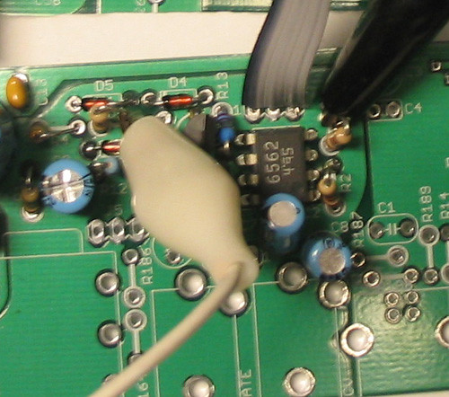
- Check the voltage at the top of where D36 goes . When the clip from R146 is disconnected
and touched to R3 again, there should be a brief pulse to 12V, if your meter has a 'max hold' setting, you can use this to see whether there is a pulse. (The picture shows testing after the VCA has been installed, but just ignore that)
Parts
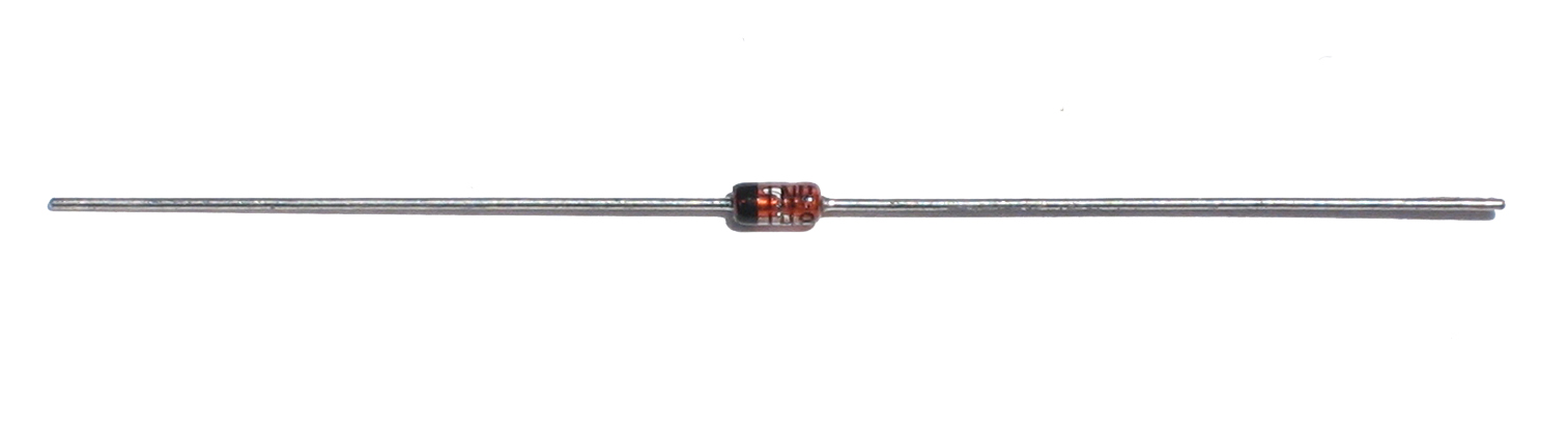 |
1N4148 | 5 |
D26, D28, D29, D34, D37 |
|||||||
|
22 ohm 5% resistor | 1 | R150 | |||||||
|
100 ohm 5% resistor | 1 | R152 | |||||||
|
1K 5% resistor | 1 | R137 | |||||||
|
10K 5% resistor | 6 | R142, R143, R144, R145, R148, R149 | |||||||
|
22K 5% resistor | 3 | R117, R146, R151 | |||||||
|
68K 5% resistor | 1 | R138 | |||||||
|
100K 5% resistor | 3 | R139, R140, R141 | |||||||
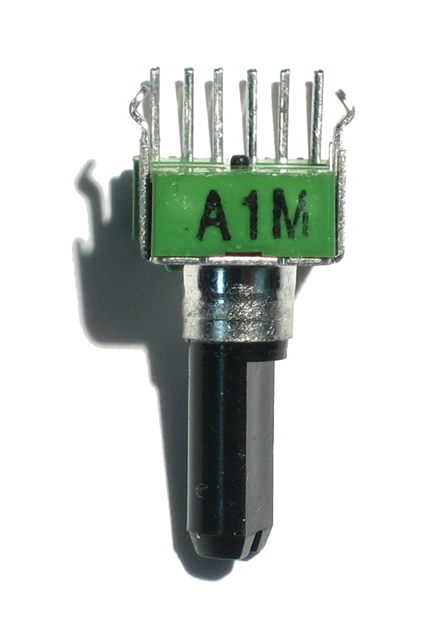 |
1Meg A (log) dual potentiometer | 1 | VR6 | |||||||
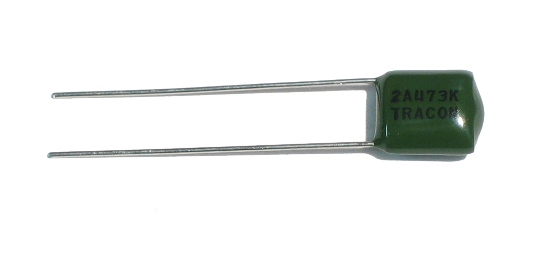 |
.047uF (2A473K) capacitor | 1 | C54 | |||||||
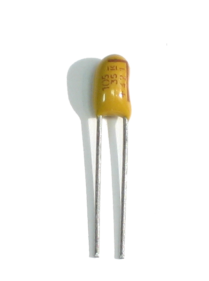 |
1uF tantalum capacitor | 1 | C62 | |||||||
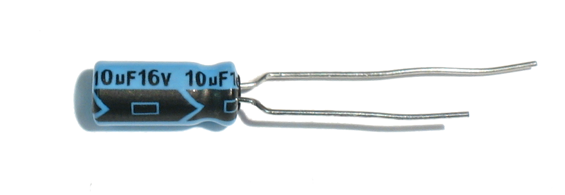 |
10uF electrolytic capacitor | 1 | C72 | |||||||
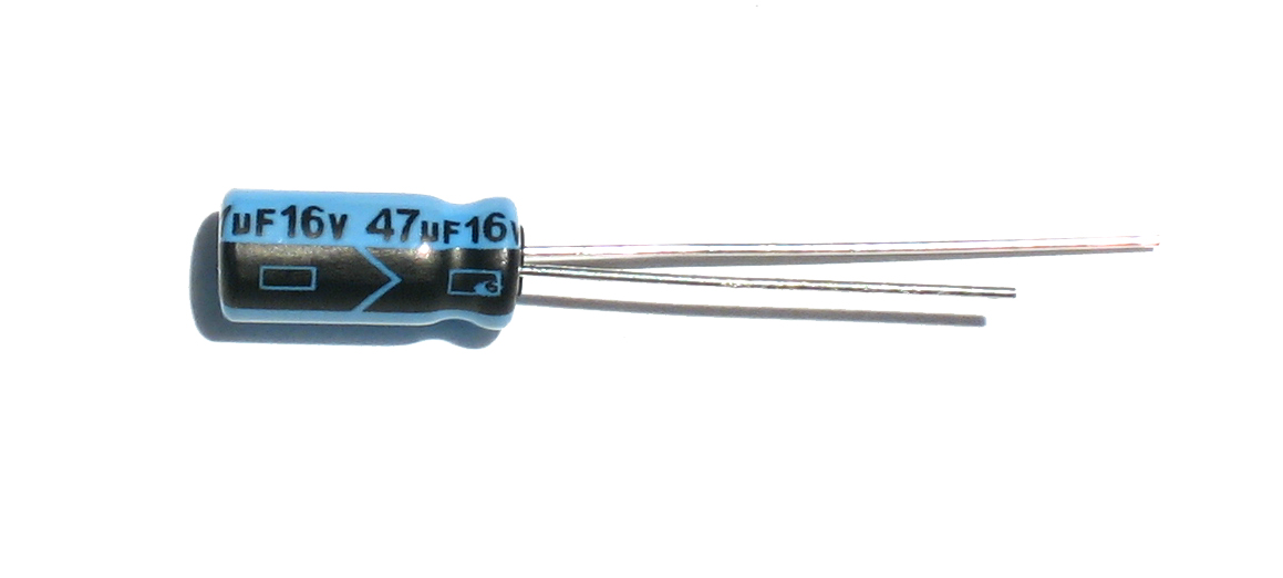 |
47uF electrolytic capacitor | 1 | C55 | |||||||
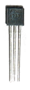 |
2SA733P, TO-92 PNP transistor | 2 | Q36, Q38 | |||||||
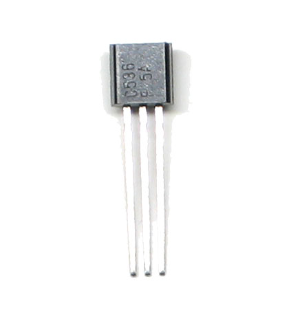 |
2SC536F, TO-92 NPN transistor | 4 | Q35, Q37, Q40, Q41 | |||||||
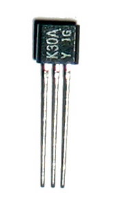 |
2SK30 JFET, must be 2SK30AY | 1 | Q39 |

