The only way to build a complex kit is to do one part at a time, and constantly test that previous parts still work. That is to say, if the VCO is failing, the first thing to do is to check that the power supply still works. However, that means you'll need to know how to test if things work!
Testing continuity: Often times you may want to check if you soldered something correctly. A guaranteed method is using the continuity checker on your multimeter. Very simply: if the meter beeps, then that means the two parts of the board you are probing are shorted together. Always test that its in the right mode by touching the tips together to verify that its beeping. This can also be used to test that things aren't connected. For example, power (ie the power supply outputs) and ground should never be continuous. When testing continuity on something like the +5.333V supply and ground, there will be a very short beep (due to the capacitor charging) and then silence.
Testing voltages: You will need a multimeter (preferably digital, although analog ones are also very useful at times) or an oscilloscope. To test a DC voltage using a meter, set it to VDC mode (see the manual) and place the tip of the black probe at the negative side of the voltage (which, unless explicitly noted otherwise, is almost always 'ground') and the red probe at the positive voltage to test. To figure out where 'ground' is (or anywhere you want to test), refer to the schematic. A nice place I used during building is R179, on the I/O board (also, pin 2 of J4). In general, if its a gigantic swatch of copper, as opposed to a thinner trace, its a 'ground plane.'
Applying voltages: There are also times when one needs to 'apply voltage' (usually low DC) to parts of the circuit. For example, testing the VCO requires applying a 1V/Octave voltage. A nice benchtop supply is best, or even a $20 kit. If you're really in a pinch, and you're not doing any fine tuning, remember that you can always use just batteries. (Of coures, they're not precise.) Always measure the voltage before applying it, just in case. Unless otherwise mentioned, all voltages are referenced positively to ground just like above.
There are 500 components in the x0xb0x (almost 100 10K resistors!) of 100 different types. The most important part of assembly is to keep the parts in order and solder them in the right place.
The 2 PCBs are silkscreened with part images and part names (although not part values). Each part name is unique, and can be cross referenced with the BOM below or in each section. In the more crowded sections there may be many part names and images and it might not be immediately obvious which part is which. However, each part name is adjacent to the picture. Therefore, look carefully to determine which part name goes with which image.
It may help to place all the parts first, verify that they are all used and then solder them in place. You can also refer to the schematic.
Remember that all resistors are named Rn (where n is some number), all capacitors are Cn, all transistors are Qn, all diodes are Dn, all LEDs are LEDn, all ICs are ICn, all switches are Sn, all large potentiometers are VRn, all trim potentiometers are TMn, all crystals/ceramic resonators are XTALn, and all jumper wires/cables are Jn. Parts should be placed over their picture and soldered on the other side.
All the large potentiometers, switches, and LEDs are on the side that faces out. The rest of the components are placed on the opposite side.
- Resistors
Almost all of the resistors are plain metal film 5% 1/4W type, cylindrical and tan with 3 color bands and one gold band. To identify the value, match the color bands to the BOM picture. Included are also a few 1% 1/4W type which are blue and have 4 color bands. There are also 2 PTC temperature sensitive resistors. They look a lot like the 1% resistors so don't mix these up! Resistors are non-polar: you can solder them any way you want. You can also check the value using a multimeter; if you're not experienced with decoding resistor color codes then this isnt a bad idea at all. - Capacitors
There are four types of capacitors: electrolytic, tantalum, ceramic and polyester. Electrolytics are cylindrical, blue or black and have a stripe indicating the negative polarity. They are polar: if you put them in backward they can explode, which is very unpleasant. The PCBs have a marking for the positive pin. Their value is written on the side (ie 10uF). The two 'dipped tantalum' capacitors are yellow and blob-shaped, they are also polar, but have a marking for the positive pin. The other two capacitors are non-polar. The polyester (green, larger) and ceramic (yellow, smaller) capacitors shouldnt be mixed. Their value may be written in 'exponential' notation so match the marking with the picture we provide. In general, the drawing on the PCB should match the size shape of the capacitor. - Diodes
There are two kinds of diodes included: 1N4148 switching (red glass with black stripe) and 1N4001 power (black epoxy with white stripe). Both are polar, and will not function properly if put in backwards. The arrow in the drawing 'points' to the stripe on the casing. The 1N4001 are used on the power supply. All others are 1N4148. - LEDs
There are multiple LEDs & they are all the same type. You may want to change the color to suit your taste, just use any bright 5mm LED. The LEDs are polar and wont work if put in backwards. The flat side in the picture matches the flat side of the LED. - Transistors
There are multiple transistors used in different packages. The analog section has two types of 5 pin matched transistors and three types of 3 pin transistors.There is no difference in the picture between the two 5 pin transistors so be sure to match the part numbers right. All of the 2SC536Fs are drawn as empty hemispheres, the 2SA733Ps have an extra line, the 2SK30s are filled in. The transistors should not be put in backwards: the matched pairs have slanted sides. The other transistors have flat/round sides. - ICs
There are many different ICs used. ICs must not be placed in backwards. For DIP (dual in line) the notched end in the picture should match the notched (or indented) end of the chip. For SIP (single inline, as in the LA4140 and BA6110) the rounded end in the picture matches the notched/indented end of the chip. They must also be soldered more gently than the rest as overheating can damage the internals: use the proper temperature and dont let the iron press against the pins for more than a few seconds each. The EEPROM and microcontroller come with sockets as you may want to replace them at some point. If you feel nervous about soldering the other chips, you can socket them too: any electronics store will carry the sockets for around $.50 each. Be sure to match the notch of the socket with the picture so that you dont put in the chip in backwards some time later. All the chips are clearly labeled on their top. - Potentiometers & Trim Pots
There are a bunch of different potentiometers, make sure to match the numbers right. The label 10KB means 10K linear and 50KA and 50KD mean 50K log. All the trim pots look alike so check the markings too. Solder these quickly because they made of plastic and can melt! - Plugs, connectors, switches, etc.
Because these parts take a lot of physical stress, it is important that they are soldered well. Make sure that there is enough solder to fill the pad and make a nice strong connection.
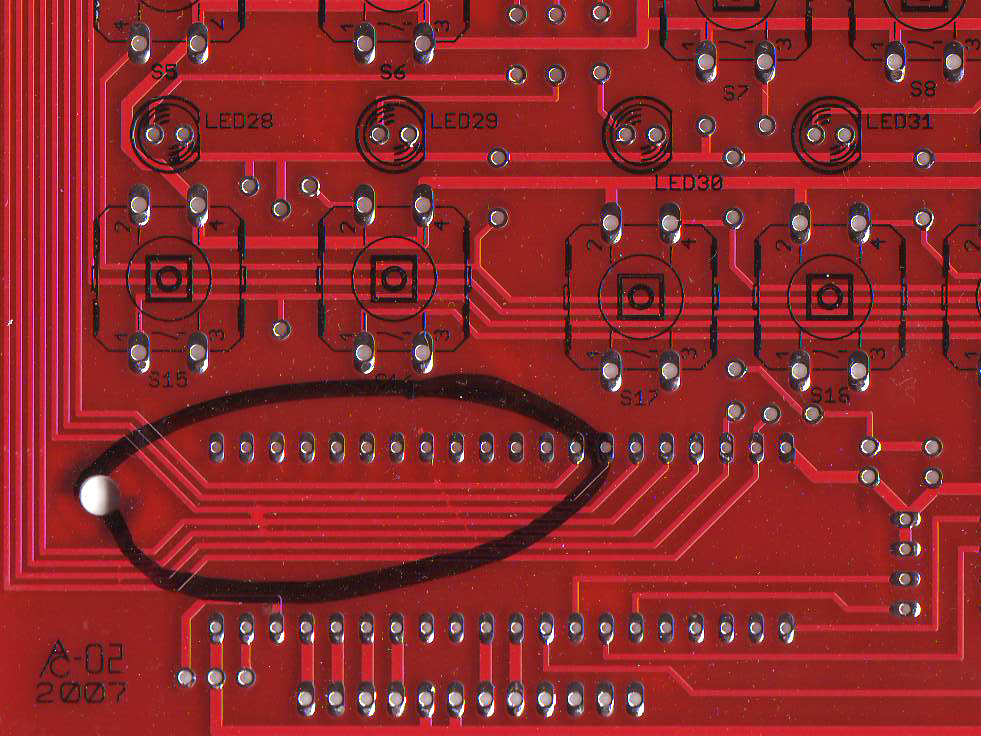
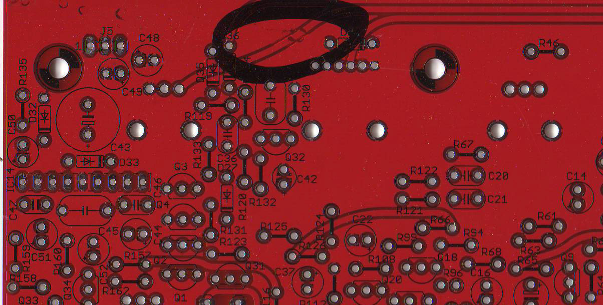
99.5% of the time, the PCB is perfect. But if it isn't, it can be a total nightmare! PCBs are tested at the factory and are visually inspected. Still it is highly suggested that you spend 10 minutes looking over the PCB for any issues.
These are two PCBs with problems, luckily found before they were shipped to kitmakers like yourself! You can click to zoom in. The first one has a splash of copper which is shorting out the microcontroller lines! The second has a 'rotted' trace, that is both shorted to ground and open. No good! If you find a problem, you should contact support@adafruit.com to get a replacement (or you can try and fix it yourself using an exacto blade and some wire.)
One good way to get a nice look at the traces is to hold the PCB up with a bright (60W+) light behind it.
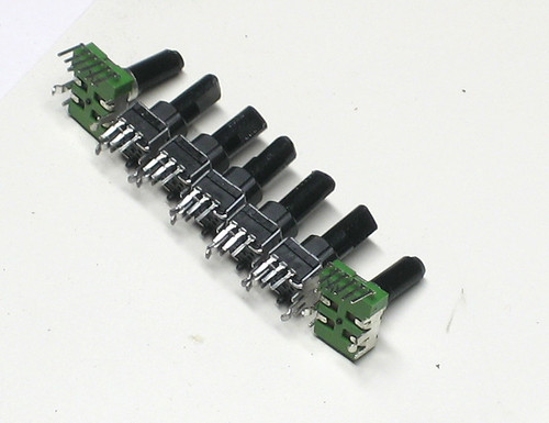
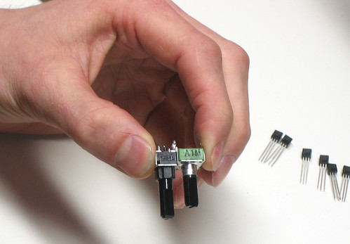
Before you start soldering you should cut down all the potentiometers to the right size!
-
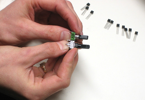
Note that there are a few different length pots, we want to make all of them as short as the shortest one. The length here is determined from where the potentiometer 'sits' on the PCB.
-
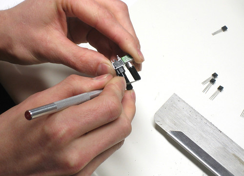
Mark the longer pots where they should be cut using a pen, scribe, etc.
 >
>
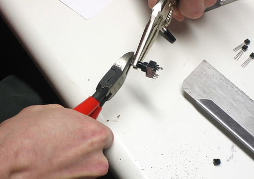
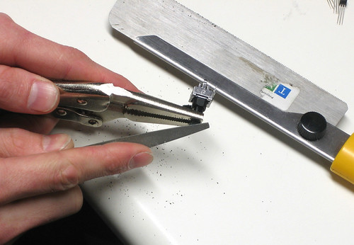
- Cut using a craft saw or a pair of dikes. Make sure to hold the pot by the shaft and not by the body!
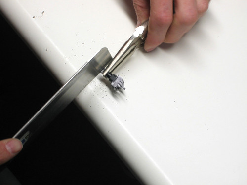
- Use a file to clean up the cut end.
- Repeat until done.